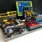
Recommended Posts

I'm also surprised to see an actual Lego cloth exists, thought as well Akiyuki was simply using some kind of random cleaning cloth :tongue:

Well, even better for the Lego purists among us!

Is part # 72965 not the same item?

https://www.bricklink.com/v2/catalog/catalogitem.page?P=72965&name=Scala Cloth Kitchen Towel&category=[Scala]#T=S&O={"iconly":0}

Share this post


Link to post
Share on other sites

It looks the same. I guess you’re right.

At first I also thought that Akiyuki used a random cloth. Last week I used google translate to translate his Japanese blog. 

http://legokarakuri.blog91.fc2.com/blog-entry-64.html

I found out that only the hoses were not from Lego. Then my search started and I ordered 3 new cloths on bricklink for a reasonable price.

Share this post


Link to post
Share on other sites

Getting very close now. The Mechanical timing is all good to go and working as it should, piping is done, lift and hopper is working well, out feed done. 

Al that remains is the last module for the cleaning cloth press and then onto the the control program that will turn the machine on and off if there is no balls being fed for a GBC display. 

Thanks @Juroen not to sure if I will be using the Lego cleaning cloth, there is non available in AU and the shipping is too high for a few cloths!

Video --> https://bricksafe.com/files/HRU_Bricks/gbc-ball-cleaning-machine-project/VID20190905224528.mp4

1.jpg  

Edited by HRU_Bricks

Share this post


Link to post
Share on other sites

@HRU_Bricks Almost done, looks very promising. Could you explain how the module is controlled by boost?


B64A7066-8BED-4F5B-A1D1-67AF99BEF876.MOV

Edited by Juroen

Share this post


Link to post
Share on other sites
7 minutes ago, Juroen said:

@HRU_Bricks Almost done, looks very promising. Could you explain how the module is controlled by boost?


B64A7066-8BED-4F5B-A1D1-67AF99BEF876.MOV

The cleaning machine does not actually need the Boost controller to operate and if can be removed all together. Thus it is the first 100% mechanical version (that I know of). There is actually not much that of the machine that was from the original, other than the overall concept and bones (flow, section positions and look). Without the original and the tips you all shared along the way it would still be a far off idea. 

What the intention with the boost controller is for it to sense when there are balls in the 4 ball lift section using the color sensor and that will switch on the PF motor that drives the valve block at the front. The valve block at the front then controls all of the functions on the machine using a combination of cylinder rams, PF switches and Servos. 

I am also using the Boost motor as a position sensor for the main pick and place arm so the controller knows when to reset the start point (full left with picking hands int eh up position. 

The Ball feeding lift is also turned on and off by the boost controller. This will run for a cycle then off for a cycle and then run for an extra cycle for each time the main machine runs. 

The main reason for the boost controller is for Lego shows so that the machine does not run when there are no balls in it as that is extra wear on parts that are not needed (that and I like to program machines too :grin:

Share this post


Link to post
Share on other sites

Major building is complete! Well hopefully *huh*

The cleaning press module is done and came out very different in comparison to Akyiuki's original. It kind of feels like it is missing something but cannot put my finger on it.....

The machine is running really well with very few balls coming and no major issues for the 1 hr I did run it. The consumption of air was not as high as I first though but still very high if you considered to use Lego pumps. Currently with an operating pressure of 1.55-1.6 bar  the consumption is about 45 Ltr/hr.

If it was not for the Powered up section it would be complete. 


Video -->https://www.bricksafe.com/files/HRU_Bricks/gbc-ball-cleaning-machine-project/VID20190909213420.mp4 

IMG20190909213513.jpg

IMG20190909213533.jpg

Share this post


Link to post
Share on other sites

Congratulations! Well done!

The thing you are missing on the press module are springs and the possibility to adjust the pressure from the press. :wink:

Share this post


Link to post
Share on other sites

It is finally complete! 100% mechanical. It is being displayed at Perth Bricktober this weekend (11 & 12 Oct 2019). A long journey and glade it is done. Now onto the Studio file....

Video --> https://www.bricksafe.com/files/HRU_Bricks/gbc-ball-cleaning-machine-project/VID20191011184813.mp4  Note there was a drone flying around taking footage

IMG20191011184724.jpg

Share this post


Link to post
Share on other sites
Just now, HRU_Bricks said:

It is finally complete! 100% mechanical. It is being displayed at Perth Bricktober this weekend (11 & 12 Oct 2019). A long journey and glade it is done. Now onto the Studio file....

Video --> https://www.bricksafe.com/files/HRU_Bricks/gbc-ball-cleaning-machine-project/VID20191011184813.mp4  Note there was a drone flying around taking footage

IMG20191011184724.jpg

Wonderful! Congratulations for this incredible machine. I hope that sooner or later there will be some building instructions available for newbies like me :)

Share this post


Link to post
Share on other sites

For years the Ball Cleaner has been one of my favorite (GBC) modules and it’s still on my wish list. Was always quite hesitant to build it because of the external/3rd party air compressor that needs to be used (guess still no-one succeeded in creating a 100% Lego compressor that can do the job). Towards the end of this year I’ll be having the opportunity to borrow an air compressor from a colleague of mine, so I’m now reconsidering to give the BC a go afterall. I do have all the genuine Lego parts in stock, but after looking at all videos/files available, I do have some questions. I know it’s been a while since you built your version, but I hope @Juroen and/or @9v system are willing to help me out where possible (since you have both successfully built the BC :classic:).

1. The air compressor I’ll be given the opportunity to use is the Hyundai 55762. Specs: 24 liters tank – motor power 750W – max. pressure 8 bar (more details/info in the link below). As I have absolutely no knowledge/experience whatsoever when it comes to using an external air compressor like this together with pneumatic Lego, would you say this one will be okay to use for the BC? Hope you can advice me a bit on this. Seems more or less the same type as Akiyuki uses.

https://www.bol.com/nl/nl/p/hyundai-stille-59db-compressor-24-liter-8-bar-olievrij-low-noise-super-silent-deluxe-versie-incl-6-delige-hyundai-accessoire-set/9300000014688403/?bltgh=o3KLl0Zhte7IFP7aBs5LpA.tJ7K6EXSyB10G-3kBSJGkw_0_16.30.ProductTitle

2. In Jeroen’s leaflet with additional info it says the pneumatic hoses are customized non-Lego parts (+/- 10 meters needed). Will the BC not work with the normal/genuine Lego hoses? Are they not strong enough perhaps? I always buy my Lego hoses in lengths of 1 or 5 meters, so wouldn’t it be possible to use those original Lego hoses and manually cut them to get the desired lengths for the BC?

3. Is it possible/advisable/recommended to first build the whole module without all pneumatic hoses and electric wiring and add all that at the end of the build? Or better/easier to include all the hoses/wiring already during the building process?

4. When downloading the files some time ago, I saved 2 versions of the pdf instructions, one containing 333 pages and the other 302 (most likely one made by Jeroen and one by Aron). Is there any substantial difference between the 2 (content wise I mean)? Or are the instructions in the 333 pages version simply split into more building steps in order to ease the building process a bit? Was just wondering which of the 2 versions I should use (assume both are based on the same Stud.io file made by Jeroen).

5. In the parts list on Rebrickable it’s mentioned that the red 8 tooth gear is meant to be the version without friction (part # 11955). Is this correct (meaning the “normal” one with friction (part # 10928) won’t do)?

6. Concerning the EV3 cables, I read that 3 standard/original Lego cables can be used (50cm each) and 3 custom made cables are needed (100cm each). Besides that there’s one Mindstorms > 9V converter cable needed to connect the PF M & L motors. That makes 7 EV3 connections/cables in total, but all 8 connections on the EV3 brick are used for the BC (4 for the motors, 4 for the light sensors). Don’t I miss one EV3 cable?

7. Is there any pneumatic and electrical scheme available, besides the info given in the leaflet and everything visible in the several videos/pictures? I refer to a scheme showing all the hoses, pneumatic switches/valves, cylinders, T-pieces, air distribution block, manometer and air tank. Just an overview showing all the exact connections between those parts would be very helpful, but I guess such a scheme doesn’t exist and it’s just wishful thinking from my end J Well, just asking… I see SO MANY hoses floating around :tongue:

8. Which EV3 program file is the final and correct one to use? I downloaded 2 versions, perhaps one by Akiyuki and one by Jeroen. The 2 versions look a bit different, so was wondering which program file you used in the end. Is the one available on Jeroen’s Bricksafe final (the one with programs “Set timing”, “Initializing” and “Running”)?

What about the 5th program (Loop 05 - “Determine if balls are available”), that is shown on one of the pictures on Jeroen’s Bricksafe? Does this code still need to be added to the rest? Isn’t this already included in loop #04 of the EV3 program?

 EV3%20code.png               

9. Is it correct that the long custom EV3 cables (1m) are used for the light sensors in ports 1 & 3 (ball detection & pneumatic switches) and the motor in port B (M Servo Motor for the linear mvmnt of the gripper)?

10. Do you roughly remember how many rubber bands and pneumatic T-pieces are used? Just an estimation as they’re not included in the inventory on Rebrickable. Looking at all pictures from Akiyuki & Jeroen, I guess the only sizes of rubber bands used are: white 2x2 (part x71), red 3x3 (part x37) and at least one green/blue 4x4 (part x89).

11. For the EV3 cables it’s mentioned we need 3 extra long ones (1m). Are also any pneumatic hoses ≥1m needed? Just to know the maximum length in case I still need to order extra hoses.

12. Port D will be used to connect the converter cable Mindstorms > 9V, but to be able to connect the Power Functions motors I assume we need 1 or 2 extra conversion/extension cables 9V > PF (20 or 50cm), correct? Just asking to be sure.

13. How does the pressure regulator underneath the inbox work? Do I set the external air compressor to maximum pressure (e.g. 8 bar) and then regulate the pressure needed for the BC to operate smoothly (approx. 1-2 bar) with Akiyuki’s built-in pressure regulator? Or should the external air compressor output less pressure (e.g. 2 bar only)?

I think it’s a great, but difficult module to build, but I’m certainly up for the challenge! Sorry for the many and long questions, but I hope your answers will take away some of the concerns I’m currently having. Like to be prepared to the utmost before starting a complex build like the BC :classic:

Hope you can help me out :classic:

Share this post


Link to post
Share on other sites
22 minutes ago, Lego_GBC_NL said:

1. The air compressor I’ll be given the opportunity to use is the Hyundai 55762. Specs: 24 liters tank – motor power 750W – max. pressure 8 bar (more details/info in the link below). As I have absolutely no knowledge/experience whatsoever when it comes to using an external air compressor like this together with pneumatic Lego, would you say this one will be okay to use for the BC? Hope you can advice me a bit on this. Seems more or less the same type as Akiyuki uses.

https://www.bol.com/nl/nl/p/hyundai-stille-59db-compressor-24-liter-8-bar-olievrij-low-noise-super-silent-deluxe-versie-incl-6-delige-hyundai-accessoire-set/9300000014688403/?bltgh=o3KLl0Zhte7IFP7aBs5LpA.tJ7K6EXSyB10G-3kBSJGkw_0_16.30.ProductTitle

2. In Jeroen’s leaflet with additional info it says the pneumatic hoses are customized non-Lego parts (+/- 10 meters needed). Will the BC not work with the normal/genuine Lego hoses? Are they not strong enough perhaps? I always buy my Lego hoses in lengths of 1 or 5 meters, so wouldn’t it be possible to use those original Lego hoses and manually cut them to get the desired lengths for the BC?

13. How does the pressure regulator underneath the inbox work? Do I set the external air compressor to maximum pressure (e.g. 8 bar) and then regulate the pressure needed for the BC to operate smoothly (approx. 1-2 bar) with Akiyuki’s built-in pressure regulator? Or should the external air compressor output less pressure (e.g. 2 bar only)?

Hope you can help me out :classic:

Hi @Lego_GBC_NL I can start by answering a a few of your questions. For reference I built the cleaning machine then decided to build a fully mechanical version that did not use Mindstorms and instead use a motor driven valve bank. 

Some answers to the questions:

1. Air compressor. The Lego compressors may run it but you will need at least 32 and they will stop working after about an hour. The compressor you mention is overkill but will work. You will need to regulate the output pressure down to between 1.5-2bar (max) otherwise hoses with blow off and you could damage the parts. I use a small air brush compressor that I bought off ebay and it works a treat (see photo below)

2. It will work with the standard hoses but the Lego hoses will not be long enough for the machine. You will also be using a lot of hose

13. Regulate the air pressure BEFORE it gets to the module and have a Lego air tank in the module as a reservoir . The built in regulator in the module is there to tell the program that the air is on and dose not regulate the air pressure. 


263577729_453019792863596_30835436620936 


My build running at a Brictober 

IMG20191011184724.jpg


Share this post


Link to post
Share on other sites
4 hours ago, HRU_Bricks said:

Hi @Lego_GBC_NL I can start by answering a a few of your questions. For reference I built the cleaning machine then decided to build a fully mechanical version that did not use Mindstorms and instead use a motor driven valve bank. 

Some answers to the questions:

1. Air compressor. The Lego compressors may run it but you will need at least 32 and they will stop working after about an hour. The compressor you mention is overkill but will work. You will need to regulate the output pressure down to between 1.5-2bar (max) otherwise hoses with blow off and you could damage the parts. I use a small air brush compressor that I bought off ebay and it works a treat (see photo below)

2. It will work with the standard hoses but the Lego hoses will not be long enough for the machine. You will also be using a lot of hose

13. Regulate the air pressure BEFORE it gets to the module and have a Lego air tank in the module as a reservoir . The built in regulator in the module is there to tell the program that the air is on and dose not regulate the air pressure. 

Hi @HRU_Bricks, yes I checked out your version of the BC as well, also designed very successfully indeed, but as far as I know there's no instructions available for that one and personally I do not own any Lego Boost equipment. Have lots of unused PF & EV3 parts in stock and with such a complex build, some decent step-by-step building instructions seem vital. Also trying to build the BC without ordering (lots of) new parts.

Thanks for answering a few of my questions!

1. Only Lego compressor I've built is the Quanix one (with 8 cylinders) and according to some GBC builders, like Jeroen, it's not sufficiant, so I'm not even gonna try :classic: Yes, the compressor I mentioned most likely is overkill indeed, but it's free and if it will work I'm happy!

2. The online shop where I buy my Lego hoses sell them in lengths of 1 and 5 meters, is that really not long enough for the BC? Looking at all pictures/videos available I don't have the feeling there's any single piece of pneumatic hose >1m, but of course I haven't built it yet, so I can be wrong. See lots of those T-pieces everywhere, so the length of the hoses is reduces by them I would say. But this is why my question #11 is there :tongue:

3. OK that's clear, the Hyundai compressor has 2 meters and apparently it's quite easy to reduce the output pressure from 8 bar to 1.5 - 2 bar. Thought Akiyuki built-in something clever for that, but seems logical to regulate the pressure before the air enters any Lego parts :classic: There's 1 Lego air tank included in the instructions, so that's also covered then. 

I'm afraid I still don't understand how the pressure regulator works. From the air inlet a direct connection is made to the blue pneumatic hose connector (part #99021), but there's no hose going out as on the other side there's this black 4L antenna. I would expect another hose going from the pressure regulator to the pressure switch on the other side of the BC... When/why is the red button of the pressure regulator supposed to be pressed and what happens if it is? How does the regulator let the program know the air is on and why wouldn't the program know this without the regulator... you see, lots of things I need to learn about pneumatics :grin:

Pressure%20regulator.jpg


Share this post


Link to post
Share on other sites

Thanks for the reply @Lego_GBC_NL

I decided not to complete instructions for my module because of the complexity of the valve bank. A gear could be out by 1 or 2 teeth and it will not run properly. It doesn't need boost, the boost module just turns the machine on an off when there is not balls, it has no control over the functions of the machine. 

To answer your questions:

2. There is no hose that would be 1m but you will be surprised how quickly you consume the hose when installing it. You will easy use 5m up. I bought 10m and used about 7ish. Can you send a link as for the store you are talking about, I need to get more and the store I bought mine from is gone.

3. The pictures you have posted are the "Over Pressure Relief Value". As the linear actuator is wound (the red ball) it pushes (F1) on the lift arm which pivots and pushes the suspension up putting pressure on the black antenna which seals the air system. When the pressure builds up (above the pressure applied to spring) it opens and releases the pressure. Note you have to put a small amount of hose on the end of the connector (circled). 

The second picture is the pressure switch which tells the program that tells the system that there is enough air pressure to start. If this is not there and the machine starts it could damage the machine. As air enters the cylinder it pushes against the shock absorber and the sensor goes form seeing black to white. 

I'll answer the other questions tomorrow. If you can think of more let me know. 

OPVR.JPG

Presure%20switch.JPG

switch.JPG

As to your previous question 11. about the EV3 1m cables,  you will use them as the cable runs are not that direct and it is better for cable management. 


Share this post


Link to post
Share on other sites

Thanks @HRU_Bricks for these clear explanations! This is helping a lot to understand the several pneumatic mechanisms that Akiyuki incorporated into the model, all so cleverly done! :classic:

2. I'm armed with +10m of Lego hoses as we speak... if I mess up cutting them too short, will buy extra :classic: Below is the link to the Dutch webshop I was referring to. They used to have a lot more pneumatic parts in stock, but unfortunately all nice stuff, like cylinders, pumps, valves, switches, manometers, air tanks are out of stock now and even completely removed from the website I believe. Luckily they still have some 1m/5m hoses available in different colors.

https://www.brickshop.eu/lego-parts/pneumaticshtml.html

3. OK, so the pressure regulator (Over Pressure Relief Value) and pressure switch are two different things and work (more or less) independently. I totally get now how the pressure switch works!

Concerning the pressure regulator (to see if I get this right): when building the BC the small linear actuator needs to be turned/wound up (just a little bit) via the red ball joint so the linkage attached (liftarm+spring) will move forward and the black antenna moves closer and closer to the blue pneumatic hose connector, resulting in a fully closed air circuit/sealed air system (thanks by the way for the hint about the very small piece of hose, quite difficult to see!). When the air compressor starts providing air into the BC and everything is fine (meaning the air pressure is not too high) nothing will happen to the pressure regulator and it doesn't need to be touched anymore (antenna won't move and can "take" the pressure). ONLY in case the pressure builds up and gets too high at some point (let's say: air pressure > pressure on the spring), the pressure regulator will pop open (antenna popping out) and the pressure is released (as a safety measure in order not to damage anything). I assume in that case adjustments need to be made (something built/connected incorrectly or too much air pressure coming from the external compressor?). Is that about it? Did this actually happen to you when you ran the Mindstorms/Akiyuki version?

11. Concernig the 1m EV3 cables: clear why they're needed (long distance, cable management etc.), but my question was more to get a confirmation that the 3 long EV3 cables are used for the light sensors in ports 1 & 3 (ball detection & pneumatic switches) and the motor in port B (M Servo Motor for the linear mvmnt of the gripper). The rest of the EV3 parts (sensors & motors) seem close enough to the EV3 brick to be able to use a 35/50cm cable to get them connected. PF motors via the converter cable (+ extension cables I suppose).

No more questions for now (13 was already enough I guess :tongue:), but for sure other questions will come to me later on... THANKS again and I like your schemes with the arrows! Very helpful!

Share this post


Link to post
Share on other sites
6 hours ago, Juroen said:

 @Lego_GBC_NL Enjoy building, if you have any questions left, let me know.

Thanks @Juroen, I'm still far away from starting the actual build, need to gain some more confidence first and I hope the answers to my questions will do that. 

Still quite some questions unanswered, but I'll take things step by step. Especially questions 7 (pneumatic scheme) and 8 (EV3 program file) worry me the most...

Share this post


Link to post
Share on other sites

7. I don’t have any schematics. It’s not that difficult if you follow the instructions on my leaflet.

8. My program with ‘set timing’ ‘initializing’ and running is the latest version, I have published. I have also made another version with ball counting.

Share this post


Link to post
Share on other sites
18 hours ago, Juroen said:

7. I don’t have any schematics. It’s not that difficult if you follow the instructions on my leaflet.

8. My program with ‘set timing’ ‘initializing’ and running is the latest version, I have published. I have also made another version with ball counting.

@Juroen, I don't have that much experience with LEGO pneumatics, so to me all those hoses look like a difficult maze :classic: Always like to be fully prepared and understanding a complex module like the BC before starting to build.

OK, I'll use the EV3 program file on your Bricksafe (“Set timing”, “Initializing” and “Running”). So the 5th program (Loop 05 - “Determine if balls are available”) isn't necessary to incorporate in the "Running" code?

To prepare the module before running I simply run programs “Set timing” & “Initializing” first and then the 3rd program "Running" without "Loop 05 - “Determine if balls are available”? Is that it?

Share this post


Link to post
Share on other sites

@Lego_GBC_NL Set timing program runs the motors in low speed so you can adjust the timing of the pneumatic switches. This is something you have to do before you run the program at normal speed. This requires some fiddling. After you have set the timing, you have to initialize the module. This sets the turntable and the pneumatic switches in the correct position before running the program. 5th program isn’t necessary.

Share this post


Link to post
Share on other sites
3 hours ago, Juroen said:

@Lego_GBC_NL Set timing program runs the motors in low speed so you can adjust the timing of the pneumatic switches. This is something you have to do before you run the program at normal speed. This requires some fiddling. After you have set the timing, you have to initialize the module. This sets the turntable and the pneumatic switches in the correct position before running the program. 5th program isn’t necessary.

@Juroen, thanks, that's clear!

One more question about this if you don't mind (sorry if it's a question asked by a pneumatics newbie with little knowledge :look:). As the "Set timing" and "Initializing" programs prepare the pneumatic switches before running (adjusting timing & setting correct start position), does this mean the way the hoses are connected from the valves/switches to the cylinders doesn't matter, considering this will be adjusted anyway after building (but before running at full speed)? 

I know the air inlet port will be the middle connection on the valve, but for the air outlet ports (A+B below), is there a fixed way to connect the hoses to ports 1+2 on the cylinder? Or, when connecting the hoses, this is of no importance as the timing will be adjusted later on if needed (meaning there's not really a "wrong" way of connecting the hoses from valve to cylinder)?

LEGO%20BC%20GBC%20-%20Connections_Valve_

Edited by Lego_GBC_NL
Change part ID of cylinder on picture

Share this post


Link to post
Share on other sites
On 8/7/2023 at 12:46 AM, Lego_GBC_NL said:

3. Is it possible/advisable/recommended to first build the whole module without all pneumatic hoses and electric wiring and add all that at the end of the build? Or better/easier to include all the hoses/wiring already during the building process?

  • I would add them as you go especially the pneumatic hoses. It will make it easier to plumb it up. 

4. When downloading the files some time ago, I saved 2 versions of the pdf instructions, one containing 333 pages and the other 302 (most likely one made by Jeroen and one by Aron). Is there any substantial difference between the 2 (content wise I mean)? Or are the instructions in the 333 pages version simply split into more building steps in order to ease the building process a bit? Was just wondering which of the 2 versions I should use (assume both are based on the same Stud.io file made by Jeroen).

  • Not sure but refer back tot eh Stud.io file as you biuild

5. In the parts list on Rebrickable it’s mentioned that the red 8 tooth gear is meant to be the version without friction (part # 11955). Is this correct (meaning the “normal” one with friction (part # 10928) won’t do)?

  • They both will work the red ones do look good there and should not slip off due to the 2x4 L beam

7. Is there any pneumatic and electrical scheme available, besides the info given in the leaflet and everything visible in the several videos/pictures? I refer to a scheme showing all the hoses, pneumatic switches/valves, cylinders, T-pieces, air distribution block, manometer and air tank. Just an overview showing all the exact connections between those parts would be very helpful, but I guess such a scheme doesn’t exist and it’s just wishful thinking from my end J Well, just asking… I see SO MANY hoses floating around :tongue:

  • I might give this a go but wont have time to do for a while....

10. Do you roughly remember how many rubber bands and pneumatic T-pieces are used? Just an estimation as they’re not included in the inventory on Rebrickable. Looking at all pictures from Akiyuki & Jeroen, I guess the only sizes of rubber bands used are: white 2x2 (part x71), red 3x3 (part x37) and at least one green/blue 4x4 (part x89).

  • I would build the module and then use what you have and buy these small finishes when done


@Lego_GBC_NL A few more answers for you. Keep us posted as you go!

Share this post


Link to post
Share on other sites

Thanks @HRU_Bricks for providing some more answers, almost there! Will sum up what I have so far :classic:

1. Air compressor => OK - confirmed the one I'll borrow will do, overkill, but will preset the output pressure on the external compressor to 1.5 - 2 bar (max)

2. Pneumatic hoses => OK - will use the standard LEGO ones (+/- 9 to 10 meters needed). Have them in lengths of 1 and 5 meters, so should be long enough for the BC

3. Best timing to connect all hoses => OK - will try adding them already while building, but this makes the pneumatic scheme even more important (question 7), will get to that later in this post...

4. Version of PDF instructions => OK - guess both versions will do the job, in case of uncertainties will indeed use Jeroen's Stud.io file to check (PDF instructions are just easier\more user friendly I would say...)

5. Version of 8 tooth gear => OK - will use the one w/o friction (#11955). Both #10928 and #11955 exist in red and it's impossible to see in all pics/vids/instructions which one is used. Both Rebrickable & the Stud.io file mention #11955, so I guess that one's correct.

6. Length EV3 cables => stll not sure what the optimal length of the 8th EV3 cable should be (besides 3*1m + 3*50cm + 1*converter cable), but will make sure I'll have at least one spare EV3 cable available (25/35/50cm)

7. Pneumatic/electric scheme\layout => OK for the electric scheme. No need to make a pneumatic scheme yourself, was just wondering/asking if someone had something prepared already when building the BC some years ago. I gave it a try myself and prepared a scheme based on all pictures, videos, Jeroen's leaflet and some common sense (I hope :classic:). Will share the scheme at the end of this post.

8. EV3 program file => OK - explained by Jeroen, know which file to use and what the different programs do

9. Long custom EV3 cables (1m) => still not sure if my assumption is correct (the 3*1m cables are supposed to be used for the light sensors in ports 1 & 3 (ball detection & pneumatic switches) and the motor in port B (M Servo Motor for the linear mvmnt of the gripper). Can anyone confirm pls? The rest of the EV3 parts (sensors & motors) seem close enough to the EV3 brick to be able to use a 35/50cm cable to get them connected.

10. Rubber bands and pneumatic T-pieces => OK - when preparing the pneumatic scheme I also got a good view on these pieces, so I do have a decent estimate now

11. Pneumatic hoses ≥1m => OK - clear answer, there are none (so cutting hoses of 1m\5m should do the trick to get all needed lengths)

12. Conversion/extension cables 9V > PF => OK - armed with 20/50cm conversion/extension cables

13. Pressure regulator => so the pressure regulator (Over Pressure Relief Value) and pressure switch are two different things and work (more or less) independently?

Concerning the pressure regulator (to see if I get this right): when building the BC the small linear actuator needs to be turned/wound up (just a little bit) via the red ball joint so the linkage attached (liftarm+spring) will move forward and the black antenna moves closer and closer to the blue pneumatic hose connector, resulting in a fully closed air circuit/sealed air system (thanks by the way for the hint about the very small piece of hose, quite difficult to see!). When the air compressor starts providing air into the BC and everything is fine (meaning the air pressure is not too high) nothing will happen to the pressure regulator and it doesn't need to be touched anymore (antenna won't move and can "take" the pressure). ONLY in case the pressure builds up and gets too high at some point (let's say: air pressure > pressure on the spring), the pressure regulator will pop open (antenna popping out) and the pressure is released (as a safety measure in order not to damage anything). I assume in that case adjustments need to be made (something built/connected incorrectly or too much air pressure coming from the external compressor?). Is that about it? 

Coming back to the most important question for me personally (question 7). Below is the pneumatic scheme/layout I prepared last weekend based on all pictures, videos, Jeroen's leaflet and some common sense :classic: Enlarged version of the pic is available on my Bricksafe page: https://bricksafe.com/pages/Lego_GBC_NL/lego-gbc/gbc-ball-cleaner-akiyuki

Please don't pay any attention to the exact position of things or the length/route of the hoses. Was too complicated to get this depicted correctly in one overview. My goal was to show every single pneumatic part (including all T-pieces) as well as all hoses and the way they're connected. Air circuit is divided into a main circuit (blue) and 4 sub-circuits going from the valves to the several cylinders. Start of the circuit is at the bottom left corner. Hope I got it all right, really curious! Would be nice and much appreciated if the BC experts could have a look at this and if I could get some feedback to see if I'm on the right track :classic:

LEGO%20BC%20GBC%20-%20Full%20pneumatic%2

Also, I especially wonder if the hoses in my scheme are all connected to the right ports on the valves & cylinders. Relates to my last question asked last Thursday:

As the "Set timing" and "Initializing" programs prepare the pneumatic switches before running (adjusting timing & setting correct start position), does this mean the way the hoses are connected from the valves/switches to the cylinders doesn't matter, considering this will be adjusted anyway after building (but before running at full speed)? 

I know the air inlet port will be the middle connection on the valve, but for the air outlet ports (A+B below), is there a fixed way to connect the hoses to ports 1+2 on the cylinder? Or, when connecting the hoses, this is of no importance as the timing will be adjusted later on if needed (meaning there's not really a "wrong" way of connecting the hoses from valve to cylinder)?

LEGO%20BC%20GBC%20-%20Connections_Valve_

Thanks a lot for your support so far, I know I'm asking a lot, but as said before, like to be 100% prepared and have a good understanding of how the module works before starting the actual build! 

Share this post


Link to post
Share on other sites

@Lego_GBC_NL

Really nice addition to the notes on this build! I think you will need to experiment and note down which side goes on what outlet. As you build the match you will be able to test the air flows as you go (label the hoses if you can, it will make your life easier).

Can I recommend for the pneumatic schematic using closed and opened symbols to make it a little clearer? (changing out the red "x"). One is caped and one is open

To answer question 13. Yes that is how it works. The pressure is relived saving the equipment and it could also reduce the pressure to the point were machine shuts down (light sensor and cylinder with shock absorber). make sure the pressure going is regulated to between 1.5-2 bar should do it. most over that will result in the rams moving too quickly. 


Share this post


Link to post
Share on other sites

Create an account or sign in to comment

You need to be a member in order to leave a comment

Create an account

Sign up for a new account in our community. It's easy!

Register a new account

Sign in

Already have an account? Sign in here.

Sign In Now

  • Recently Browsing   0 members

    No registered users viewing this page.