
Search the Community
Showing results for tags 'powered'.
Found 6 results
-
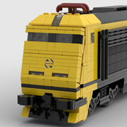 Hi, After just finishing the S-130 Project I´ve already decided to start a new one. In this case this is going to be the Renfe Class 309, a small 3 axle shunting locomotive from the 1980s. This quite a big contrast with the S-130 but I think is a perfect little project. This is the train in question: The main challenge on this project is how to power it, in this case I´m thinking about using Circuit Cubes to power the three axles. For the running gear design I decided to based it in the one made by @jtlan for his TP56 Switcher Locomotive as is one of the only examples of a 3 axle shunter that I found. Even with this base as a starting point is not easy to do this as my design is just 7 stud wide so I need to offset everything. This is a rough assembly that I have done for now: As it can be seen, the motor will be placed on the front and the battery is going to be right behind, the idea is to use them as counterweight for the heavier cab which is located on the rear just behind the last axle. And now it comes the part in which I ask for some help: Even though I have the design mostly figured out (I might need to make a prototype to see if it can work through R40 curves) my main concern is with the Circuit Cubes Motor and their power output and speed. This is a shunting locomotive so it´s not going to be as fast as the S-130 but even then, it seems that they are quite slow and might require a 1:2 gear ratio which can be simply added onto this design. My concern with this is that is going to become severly underpowered and wont be able to pull any load. I´m not expecting to pull something as massive as the S-130 cars but I would love for it to be able to maybe pull at least one of the passenger train cars that I´ve already designed (although I´m not planning on building them any time soon). This cars are massive with a weight of 1kg each, but those were the real load for this locomotive on the past. I´ve already tinkered with the idea of adding two motors but that will require a much complex redesign as I need to keep the middle axle powered through a worm screw to make it able to work through R40 curves. In this case I think there is enough interior space for me to not worry about it: I would like to know if anyone has done a proper test of the Circuit Cubes motors and knows their maximum load and speed. For now I´m going to continue working on the one motor design and make plans to order pieces for a small prototype. Imanol
 -
 Full Album: http://imgur.com/a/YdL5x Specifics: 4x L Motors RWD (Geared Up 1.2x) Full Independent Suspensions 6x Shock Absorbers 2x AA Battery Box 2x V2 IR Receivers Frontal Led Lights Differential Weight: 1250g (with batteries) The Idea is to create an Heavy-Weight Buggy with good performances using no expensive pieces (Buggy Motors, SBrick..). The final speed is acceptable, the torque has some difficulties in uphill but for the plain is sufficient, and the maximum speed is reached quickly. I called it Fury Road because it reminds me so much the style of Mad Max vehicles. I know it's a little be "naked" but I like it in this way. I putted in it some lateral exhaust pipes, a little spoiler, a cabin and some lights to improve the aesthetics. I tried to put the IR receivers in a position that seems a big engine that comes out. Hope you like it! ;)
 -
 I didn't build any MOC for a while. This is my lastest MOC of wind powered series on youtube cannel. Maybe this is world first Lego wind powered two legs walker. Hope you lie it ;) Update to V11, smaller leg design. Update to V9, much faster walking. Update to V6, add piston, high efficient four blade fan, but high wind resistance design. Update to V5, exchange belt with chain drive. Update to V4.1, add fake Mr. gold and bicycle rotate wheel. Update to V3, can walk toward wind source. Lego wind powered walker robot v4 by cmfkian, on Flickr Lego wind powered walker robot v4 by cmfkian, on Flickr
 -
 Hi everyone, I'm searching for the best motor to measure angles. Since I don't have all motors, I'm depended on those, who have them and could a comparison. Requirements: The motor must be compatible with the C+ Technic Hub, used for example in the 42100 The resistance, when turning the motor manually, has to be as low as possible When the motor is turned manually and you stop turning, the motor should not continue to turn with too much swing. 2. has more priority than 3. I have tested the C+ L and XL motor so far. I also have the large angular motor, but it is simply too large. The internal resistance of the C+ L motor was way to high. The C+ XL motor delivered quite ok-ish results. It is just too bulky. Perfect shape and size would be the Medium Angular Motor, which I don't have. Another alternative would be the Boost Medium Linear Motor. I would appreciate, if someone, who has these motors, could do a test for me. A little teaser why I'm looking for this info: I'm building a truck with pneumatic suspension. I using the angles of the suspension arms to detect and control the height. First proof of concept in PoweredUp is already written and working.
 -
I'm missing a place where Powered Up code can be gathered and explained so other guys can reuse it or find inspiration. I had a discussion with @Jim how that could work out in this forum. I was thinking about having something like the hall of fame for code which underwent optimizations in a dedicated thread and which was proven to work. But this might lead to several thread which are prone to be inactive. So we decided to start with a single thread to publish PU code and discuss it. If it gets to chaotic We could have two separate thread. One for discussion and help request and the other one for working and optimized code. To keep things orderly, a general structure might be helpful. So here we start with my proposal. TL;DR: Automatic brake lights based on speed reduction Description: The following code switches brakes lights on in case the speed is reduced. That works for reducing speed while driving forward and backward. When the speed reaches 0, the light are turned off. In this code I'm using PF lights controlled by the Boost color and distance sensor. But that can be replaced with PU lights. Code: Video Declaration of variables: a - Used to control the speed, is set by the slider 0 b - Speed (a) at the first point in time c - Speed (a) at the second point in time d - Speed difference between b and c Detailed walkthrough: The code block consists of three rows. The first row consists of a loop (left) and the code block to control the speed of the motor (right). Most of the code blocks in the loop are not needed. You actually just need the first block which sets constantly a value for the variable a to control the speed. The rest are widgets for testing timings. The second row is the logic to detect speed differences. To do that constantly, a loop is used again. It simply reads a, the speed at different times. You can adjust the time between the measurments according to your needs. In my case 0,08s worked well. At the end of the loop the difference is set to the variable d. The value can be something between 100 and -100. The third loop at the bottom contains the logic to turn the brake lights on or off. You will also notice the purple blocks. They are used to control the PF lights. I'll come to that in a bit. First i want to explain the logic to turn the lights off an on. There are three scenarios: Driving forwards Driving backwards Parking When you are driving forward the max value of a is 100. Lets say the speed is suddenly reduced to 50. The difference is 50. When you are driving backwards the max value for a is -100. The speed is again reduced by 50. The difference is -50. When you are parking the difference is of course 0, because it doesn't change. So i have two condition i want to check for: Am I driving backwards or forwards? Is there a speed difference? I can exclude the third check, parking, by checking values for a that are greater or smaller than 0. So, in one sentence: IF there is a speed difference AND the speed is GREATER THAN 0 OR IF there is a speed difference AND the speed is SMALLER THAN 0 then turn on the light (upper purple block at the end). But how to control PF lights with Powered UP??? That is covered for example by @kbalage here. The first purple code block on the left sets the port and the correct mode for the boost sensor. The two purple code blocks on the right side control the brightness of the PF lights. D is the port where the sensor is connected to, 3 is the channel 4 on the PF IR receiver, 5 is the red or blue port on the IR receiver, 7 switches the light to max brightness, 8 turns it off.
-
Base on Amida's Pegasus Automaton. These are some wind powered (cars) modification. Hope you like it. ;-) Original Amida's Pegasus Automaton LDD simulation. Move toward wind, difficult one. Amida 's Pegasus Automaton LDD simulation: http://www.eurobricks.com/forum/index.php?showtopic=100029entry1997835