
anyUser
-
Posts
247 -
Joined
-
Last visited
Content Type
Profiles
Forums
Gallery
Everything posted by anyUser
-
 Me - but it's just too big to regularly play with it. So I stopped after some test drives.
 -
Can you tell if the XL motor turns when in drive mode or does it appear to stall? (Check gearbox and listen to noise from motor) If the motor is not turning it could be - wrong - alignment of the differentials
-
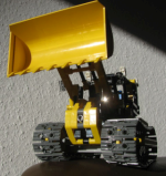
42116 Skid Steer Loader
anyUser replied to JintaiZ's topic in LEGO Technic, Mindstorms, Model Team and Scale Modeling
I was aware that putting in the black panels would give colour scheme similar to the JCB above. Perhaps a few more pieces need to be put in black (cabin + towards the back). But I wanted it more 'friendly', e.g. bright. I have most of the available parts in Bright Light Orange - but some just haven't been made. -
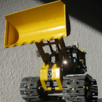
42116 Skid Steer Loader
anyUser replied to JintaiZ's topic in LEGO Technic, Mindstorms, Model Team and Scale Modeling
my attempt on black & yellow version: Conversion into a fork loader seems feasible. -
42117 Race Plane
anyUser replied to JintaiZ's topic in LEGO Technic, Mindstorms, Model Team and Scale Modeling
To me gearing is not necessary: because of the small wheels the propeller is spinning quite fast. Colour variant: The plane is - due to its size - very "swooshable" but technic function obviously only works on the runway. -
Shouldn't there be two of the white 1L 'beams' covering the 4L axles?
-
30465 Helicopter
anyUser replied to msk6003's topic in LEGO Technic, Mindstorms, Model Team and Scale Modeling
All, thanks for the additional pictures that helped to finish my version: As you will notice I changed the center gears to have the tail rotor turning faster than the main one. -
LEGO 8640 Update
anyUser replied to Thirdwigg's topic in LEGO Technic, Mindstorms, Model Team and Scale Modeling
This adds a nice touch to that old set. I found it rather bland as it only had the turning function of the main and tail rotor. I would like to build it myself. Isn't helicopter pilot typically sitting on the right side of the cockpit? -
42121 Hydraulic Excavator
anyUser replied to Ngoc Nguyen's topic in LEGO Technic, Mindstorms, Model Team and Scale Modeling
It works quite smoothly when I put 8-tooth gears on the top: -
General Part Discussion
anyUser replied to Polo-Freak's topic in LEGO Technic, Mindstorms, Model Team and Scale Modeling
I used dark azure in my attempt. I think that greenish hue is missing with respect to catalog pictures: -
42121 Hydraulic Excavator
anyUser replied to Ngoc Nguyen's topic in LEGO Technic, Mindstorms, Model Team and Scale Modeling
I'm not sure abour the distance between superstructure and tracks. Image suggests no distance: But there I found that superstructure will touch track elements especially if boom is extended. If I increase distance it doesn't look like the photo from catalog: On second thought: Are there 16-tooth gears in the upper (track) beam or is something smaller used? -
42117 Race Plane
anyUser replied to JintaiZ's topic in LEGO Technic, Mindstorms, Model Team and Scale Modeling
I am not a big fan of turqoise technic pieces, too. If my draft is close to 42117 there should be quite a bit in the center to stabilise the model.I haven#t figured out how to set up the rear wheel. -
Did you consider to chose a different colour for the lower / bottom: Maybe (light) bluish grey?
-
Technic Model Comparison
anyUser replied to Ngoc Nguyen's topic in LEGO Technic, Mindstorms, Model Team and Scale Modeling
although I prefer this one: -
[HELP] Generic Building Help Topic
anyUser replied to Jim's topic in LEGO Technic, Mindstorms, Model Team and Scale Modeling
Just tested: With not-fresh batteries: No. PF L and PF Servo could. Remark: pneumatic switch (from 42080) was hardly used. -
[HELP] Generic Building Help Topic
anyUser replied to Jim's topic in LEGO Technic, Mindstorms, Model Team and Scale Modeling
If you got that far you could also set up the control+ hub: Put in the batteries (iset on page 222) and connect the cables as described in step 344 respectively 347. If you start the control+ app a firmware update will be written to the hub. This can be recognized by the red / green / blue changing of the LED. If the hub is ready the indicator will change to a permanent blue. Select the interface for the hauler. It will open in the setup screen to calibrate the motor. This includes a backward / forward test drive. Do not worry: It will take less than the + / - 1 m space. My truck was moving only about 40-50 cm. The calibation should finish sucessfully even though the linear actuators aren't connected yet. -
[HELP] Generic Building Help Topic
anyUser replied to Jim's topic in LEGO Technic, Mindstorms, Model Team and Scale Modeling
Hello, if your description refers to observation made when pushing the truck - e.g. not using the motor to move: This is perfectly OK. The drivetrain is powered via the dark grey differential between rear axles and front one. The propulsion input to the differential housing is always connected to the motor that works as a stop at this point. Therefore the two output sides of the differential are rotating in opposite directions if wheels are turned by hand: You cannot push the hauler by hand. You need to activate the motor to have all wheels turn in the same way. Verify that you have aligned the differentials as shown in step 340 on page 219. When I lay my hauler on its side and spin on of the rear wheels, the other rear wheel rotates in the same direction and the fronts wheels rotate in the opposite direction. The housing of the grey differential, e.g. the 24-tooth side of it, are visible from the bottom: It does not turn. -
Trying to decide...
anyUser replied to Snazzy Bricks's topic in LEGO Technic, Mindstorms, Model Team and Scale Modeling
Depend's on what you refer by "it". Width and lenght of 42108 and 42112 are similar. But because the crane is shallow (flat) model I find it difficult to tell (without reference to real world machines). And it is a nice motivation to look for and build further cars to put on the decks. -
Trying to decide...
anyUser replied to Snazzy Bricks's topic in LEGO Technic, Mindstorms, Model Team and Scale Modeling
I don't think so. I would place 42093 at the same scale as 42009 and, of course 42098. 42112 is similar to 42078 and 42108. Both are considerable smaller than 42098: -
I measured 120 cm for my 42112 and 65 cm for the modified one :-)) I started this topic some time ago. I'm stuck because my setup cannot move the drum. I read about changes in the electronic instruction in a lego forum. My box shows "425S0" and I've got the 3.2L axle + tile setup. Fun(?) fact: When I started to measure the turning radius the truck wouldn't move at all today. The drivetrain was jammed by the pistons. It was working fine when I stored it away some weeks ago.
-
I rebuilt the whole chassis. This is the best that you could get with 12 tooth gear on 7L tooth bars: The steering on the original set is limited by multiple elements: a) Step 15 (p 14): The white 1L beam would pose restriction b) Step 20 (p 18): The white 1L beam in combination with the two orange 2L beams (cf. Step 44 on p 38) would pose restriction c) Step 24 (p 20): That grey beam restricts the movement of first axle steering to a tiny bit. d) The chassis itself would prevent large steering angles. I think I found three spots where the wheels will touch beams at full steering lock. One of the (lowest in picture) is part of the drum gear box. (left: my steering setup, right: setup from instructions) Disadvantage: My setup uses four gears to achive different steering angles. Straight alignment is somewhat difficult.
-
42113 Reconstruction Guide
anyUser replied to Ngoc Nguyen's topic in LEGO Technic, Mindstorms, Model Team and Scale Modeling
Brickshelf appears to be down (un-reachable) for the past few days. I put the images somewhere else. (Sorry no direct linking because with some browsers mixing of https and external http servers is blocked by default and thus images not shown.) -
The cement drum is a really heavy weight that has to be moved. I did some test driving with the drum on both versions: Neither of them could turn it. Gears are slipping: a) 12 tooth half bevel to 12 tooth bevel respectively b) 8 tooth gears that form the ratched To fix either of them I think I have to add bracings to hold gears in place. As these are deep within the chassis I may have to redesign the whole gearbox.
-
That is not a 3M beam but a 3x3 T-Beam.
-
Whatr about the drawings issue by Lego: