

mudseason
-
Posts
36 -
Joined
-
Last visited
Content Type
Profiles
Forums
Gallery
Everything posted by mudseason
-
Hello, I'm really struggling with servo calibration. I have build a MOC (kind of racing prototype) using a PU Large motor for steering. The MOC is powered by two Buwizz 3.0 as I use the 4 PF ports to power 4 buggy motors. After having spent some time with the servo calibration failures (half turn and then nothing else) I eventually found out a working PU port. Despite the calibration being successfully completed (+90, -90 then center). I have two main issues: - it seems I'm only able to use the steering if I connect the Xbox controller. - Once I drive the MOC, the steering does not return to its zero position when I release the joystick. It only goes towards the center a little bit. Any help is greatly appreciated. Thanks.
-
10300 BTTF DeLorean DMC-12 Time Machine
mudseason replied to Polarlicht's topic in Special LEGO Themes
Thanks, looks better but the side view still put me off. It looks like a car was mod into a pickup. There's something goofy, I cannot explain it better. Most probably it cannot be done better a this scale, I'm not blaming at all the designers, I think it's a great detailed model. -
Hi, the one below is my motorized version of the model. 2 Buwizz 2.0 4 Chinese-replica of buggy motors 1 Servo motor (PF) I obviously started from the Buwizz instructions and adapted to the PF servo motor and to the various body works adaptations e.g. engine hood nose wing white stripe rear wing no yellow/blue parts brakes calipers 1647937125975 by _mud season_, on Flickr 1647937125959 by _mud season_, on Flickr I hope you'll like it.
-
Late to the party. I hope you enjoy my mod. Interiors and structural changes are from Edge of Bricks (you can find his moc on rebrickable). Exterior I took inspirations by non-Lego models and a few stuff on the back from Killasudle (the phones ;-) 1647937126007 by _mud season_, on Flickr 1647937125992 by _mud season_, on Flickr Hope the links work! bye
-
10300 BTTF DeLorean DMC-12 Time Machine
mudseason replied to Polarlicht's topic in Special LEGO Themes
It's just me or the side windows are just off proportion wise? I find it too short. I like the model, but that detail is definitely wrong and I can't stand the side view. -
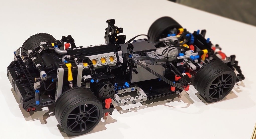
Small update. I completed the chassis. I confirm that it can go straight even if the motors are not perfectly identical. it also drift, I hope the link works. I will now focus on the body work. Here the link to a short animated GIF of the car spinning in "Normal" speed. https://imgur.com/a/lGYE5mY In fast you have to watch not to trigger the over protection. In ludicrous... I have not had the courage to try.
-
Yes, I will report the results for sure. Thanks for experimenting!
-
the vehicle I plan to build is a road vehicle. Now the point is the definition of "smooth". If the observations done by "ord" are accurate, that 5% may provide a "smooth-enough" experience. If that 5% deviation support slides instead of jumps than it may even provide a "fun-enough" experience.
-
Thanks a lot, this was very informative. Furthermore I checked the forum and I failed to find, collected in a single thread, all those details. I hope this thread will also serve others. BTW: connected driving axle is not good even on a small footprint car: I tested it on a two L-motors modded Fiat 500, I did the mod for fun and the car was jumping while turning! No jumps when I further modified it using a differential.
-
Thanks for the reply. Nope, the mod is for a pure rwd. However left and right wheels are driven by individual RC motors that are not interconnected. Actually each wheel is driven by a pair of RC motors, but this Is a detail. The point Is that there Is no connection between left and right whatsoever. Hope this clarifies.
-
This may sound as a dumb question, and probably it is. It happens that I have two buwizz 2.0 currently parked and the 42125 set. I'm now thinking about modding the set following the instructions by the buwizz team and some ideas I have to turn it into a sort of 488 pista. However I see that the drive train does not make any use of differential. I wonder if the terrain friction is enough to equalize the rotation of the two independent driven wheels or if the resulting model is going to wander left/right instead of going straight. I never built an independently driven drive-train so far, I don't like the idea from a mechanical perspective, but if it works it works and I saw more than one model adopting this kind of approach.
-
dumb question. No differential, correct? Isn't it an issue?
-
Got mine Yesterday, really nice and working great. Unfortunately I discovered that one of my four Power up motors is broken and I cannot yet check the model. I have a question, did I get It right that the Speed modes are no longer effective even if I can select them in the application?
-
yes, I'm sorry that my comment sounded a bit lame. I know very well that buwizz 2.0 is a great product and I expect buwizz 3.0 being even better. Obviously you did your evaluations to set the tag price, price that shall not only encompass the HW part, but also the SW one. I just had a "small" letdown moment after the excitement. So to switch to a more technical question: do you confirm that 1 unit can drive: 4 PU large motors + 1 PF servo ? thanks.
-
I was going to preorder the beast to power my modded 42099: geared up 2 times, but with 4 motors instead of 2 + an old servo for steering >> perfect match for the buwizz 3.0 I would also have a spare connection for the lights... ,.. then I crashed on the price, 181eur on pre-sale (sorry, but I have to include vat). does any pre-sale coupon for pre-pre-sale exist that I have missed? Returning customer loyalty something? That is going to be my 5th Buwizz ...
-
BuWizz and Powered Up
mudseason replied to mudseason's topic in LEGO Technic, Mindstorms, Model Team and Scale Modeling
thanks kbalage, seems my best option is: keep the PU motors replace the PU servo with a PF servo buy a pair of adapters feed everything with a buwizz. -
BuWizz and Powered Up
mudseason replied to mudseason's topic in LEGO Technic, Mindstorms, Model Team and Scale Modeling
correct, that's the cable. They're expensive and do not work for servo As I'm just looking for providing more juice to the motors (11-12V) a different approach could be to use an external battery and bypass the hub voltage limiter (if any). Was that already attempted by someone? -
Hi All, title is already self explanatory. I know that it is possible to connect powered up motors to a buwizz using dedicated adapters. What about controlling a powered up servo with buwizz? Is that possible? I did I quick search but did not find anything so specific. Thanks.
-
Effe's MOC Corner
mudseason replied to efferman's topic in LEGO Technic, Mindstorms, Model Team and Scale Modeling
Interesting. Did anyone have success in feeding a powered up set with a buwizz? I mean, the motors can be connected with an adapter, but what about the servo? -
AWD - independent axles
mudseason replied to mudseason's topic in LEGO Technic, Mindstorms, Model Team and Scale Modeling
Thanks Astyanax for the info, very interesting. I removed the wheel to check it and, that's exactly how it works. Just less than half a stud total motion for complete excursion. Beside this, the system has a double offset: on the wheel hub side it is outward on the car body side is inward; I do not know if this is "averaging" so that the sliding effect is minimized. As 'm trying to mod the front axle I fear I cannot exploit this workaround due to the steering mechanism. The top arm pivot cannot be pushed to the right (see my picture), but... may be there's a solution: in the drawing I'm using the old female/male on the car body side. The female seems to be 3 studs long. However the new CV female joint seems being 4 studs long. If this is true then I would have full alignment on the pivot points. -
AWD - independent axles
mudseason replied to mudseason's topic in LEGO Technic, Mindstorms, Model Team and Scale Modeling
Question, in the "original" model the rear pivot points, for the suspensions, are one stud off (inward) from the pivot point of the CV joint. There are two pairs of lift arms two above and two below, symmetric to the CV joint. This is the picture (for simplicity it reports only one arm, but you can see that the arm connects one stud inward re- the actual CV joint). http:// Is that sub optimal, and the suspension pivot shall be exactly on the same line as the cv mating? In the 42099 all CV joints and suspension pivots are exactly aligned. Now, leaving aside the drawings, back to real life, I have the car in my hands, and the rear suspensions... work like a charm. My conclusion is that one stud offset is sub optimal in terms of freedom of movements, but for a racing car the limited working angle is acceptable. Under the above assumption, I planned this kind of solution for the front, as you can see the pivot point is offset one stud (outward): http:// What do you think? Thanks a lot for the support you all are providing. Cheers. -
AWD - independent axles
mudseason replied to mudseason's topic in LEGO Technic, Mindstorms, Model Team and Scale Modeling
I have the 42099... just copyed the idea from that very model. Regarding the wheel hubs, it looks like that to have the joint where the steering pivot is I should couple in the following way: Wheel + Portal Axle then... 92909(Hub)-> 32494(CV Joint M, old) -> connecting axle -> 52731(CV Joint M, new)-> 52730(CV Joint F, new) So I will need to use the old CV male joint to the hub as the only hub that directly supports the new CV male joint is the one with planetary of 42099. Would you confirm that? -
AWD - independent axles
mudseason replied to mudseason's topic in LEGO Technic, Mindstorms, Model Team and Scale Modeling
I see the issue with the pivot for steering. I will fix it,it is quite obvious now that you said it. I will def use the new CV joints, I just miss them in my library. Furthermore, the second steering link is not "driven" and does not use a gear rack, just a lift arm sliding. The one driven is only the one on the front. The 8 tooth gears are only used to lower the axle. Thanks a lot. Cheers. P.S. I removed the pictures in previous post, I could not stand their vision... ahaha Thanks again I will correct it, most probably by using a different wheel hub and including. Just to be very clear, the drawing is intended have a rough picture and buying the parts and spot big mistakes like you did, I will then experiment with actual parts. -
AWD - independent axles
mudseason replied to mudseason's topic in LEGO Technic, Mindstorms, Model Team and Scale Modeling
And this is my attempt. I expect it to be full of naïve and/or wrong implementations, in case you think anything is wrong or should be differently done, do not hesitate to suggest different solutions. Some note: - white parts are from the original car and I preferably do not move them (some cannot be actually moved as support other parts). - the wheel hub is the part 23801, but I do not have it in my LDCad library. - check the steering solution; the original car (it is the Mantis model by astyanax) has not the double link solution, I wonder if the added bar would just make it more complex without benefit or it could help - to save time I just partially completed one side, and skipped the very obvious connections with pins. I do not know how to upload the LDCad file, I'll keep it on my Gdrive for a while: Mant6_front_axle_20200526.ldr Here some pictures: [picture removed as I could not stand the vision] ;) Thanks, Cheers. -
AWD - independent axles
mudseason replied to mudseason's topic in LEGO Technic, Mindstorms, Model Team and Scale Modeling
thanks to all... back to modding then. byez.