
Captainowie
-
Posts
502 -
Joined
-
Last visited
Content Type
Profiles
Forums
Gallery
Everything posted by Captainowie
-

GBC General Discussion
Captainowie replied to Jim's topic in LEGO Technic, Mindstorms, Model Team and Scale Modeling
Wow, that's a dense layout. -
I made something very similar to that, and put it on floats for a LEGO boat race. It came last of the finishers (but at least it finished!) but generated much discussion.
-
Lego Boost Übertopic
Captainowie replied to mahjqa's topic in LEGO Technic, Mindstorms, Model Team and Scale Modeling
It's Turing Complete - what more could anyone want? :-) -
GBC General Discussion
Captainowie replied to Jim's topic in LEGO Technic, Mindstorms, Model Team and Scale Modeling
Zamor spheres and the balls that come with Mindstorms have that large indentation. You _can_ make a GBC out of them, but it's trickier. -
No, the power source is not irrelevant - some types of batteries have a significant voltage dropoff as they start to lose charge. When you're measuring such small differences between motors, that might make a measurable difference, especially between the first and last tests. In any case, an easy way to test two motors against each other would be to have each motor driving one side of a differential - the speed of the diff cage will be proportional to the difference in speed of the motors. Owen.
-
Hi Darryl That is a difficult question to answer. I've been pondering it on and off for a while, and while I haven't sat down and proved it for Technic, I suspect that the logical grouping would require more than three dimensions. To illustrate, with normal LEGO bricks, you'd need a three-dimensional storage system - one each for length, width, and colour. For example, you could have a chest of drawers, with red bricks in the top drawer, blue bricks in the second drawer, yellow bricks in the third drawer etc. In each drawer you'd have an array of containers, with 1xn bricks in the first row, 2xn bricks in the second row, in general, kxn bricks in the kth row. In each row, you'd have kxk bricks in the first container, kx(k+1) in the second container, and so forth. If you add sloped bricks into your collection, that makes for a fourth dimension that you need to logically group your parts. With Technic, consider the set of axles. You'd have one dimension for length, another for colour (gone are the days when they were all black. Gone too are the days when even lengths were black and odd lengths were grey), and another for whether or not the axle has a stop or collar. Now consider the set of pins. You've got one dimension for length, one for whether or not it's got friction ridges, and one for whether or not it's an axle pin. That was before the advent of the 3L pin with axle, and the 3L axle with pin. Clearly in the logical system the 2L axle needs to be adjacent to the axle pin, which means that the whole axle family needs to be orthogonal to the pin family. And then you have the pin-with-pinhole part, which clearly needs to be adjacent to the 1L beam, and adjacent to something in the 2L pin family, which means that the whole beam family needs to be orthogonal to the whole axle/pin mess. In the end, you're limited to the space you have, and only three dimensions, so how you choose to proceed will be determined largely by which constraints you choose to ignore. There are many things discussed in the how-do-you-sort-lego thread that you may find useful (and which this thread is destined to be moved to, if people keep posting "here's how I sort my LEGO"). As for the names of the elements, that's not much easier. There's the internal LEGO name, part number. There's the LDraw name and part number. There's the Bricklink name and part number. There's the Brickset name and part number. Some of these names and numbers are even the same between datasets! Good luck. If you manage to find a general solution, please let us know! Owen.
-
Technic Link Tread 3873
Captainowie replied to knotian's topic in LEGO Technic, Mindstorms, Model Team and Scale Modeling
There are lots of ways to attach things to those treads, but each with their own challenges. As you've found, you can put a tile or plate over the links. 1x3 plates work too, but they're not much better than the 1x4 case. There are elements that are small enough to go through the holes in the tread - I've used pneumatic T-pieces here. I think anything that clips into a minifig hand should go through those holes. Finally, the tread link itself fits snugly into a technic hole. You might be able to get what you want by using some of the wide variety of technic connectors etc. Hope this helps Owen -
Torque question
Captainowie replied to tomek9210's topic in LEGO Technic, Mindstorms, Model Team and Scale Modeling
A M motor geared down 1:3 goes at pretty much exactly the same speed as an XL motor geared down 3:5, and the XL motor will have significantly more torque at those speeds. -
That's one use for it, sure. But you could certainly use a diff in this case too, with one output moving the arm back and forth, and the other output rotating the blade. As long as it takes more torque to rotate the blade than it does to move the arm, then when the motor turns forward, the arm moves out until it hits its stop, then the blade turns - the reverse happens when the motor turns backwards. You could possibly add in a ratchet if you didn't want to have the blade turning when the arm is retracting, but then you stall the motor when the arm retracts fully. Owen.
-
GT3 Racer (wip)
Captainowie replied to Aventador2004's topic in LEGO Technic, Mindstorms, Model Team and Scale Modeling
If that's your motivation, then you're doing it wrong. Build for yourself, pay no heed to a bunch of anonymous strangers on the Internet. -
Beautiful. A masterful improvement over the original in every way. Owen.
-
I am surprised you couldn't find _one_ eleven year old keen to drive a robot around. I would have loved to do that as a kid (heck, I'd probably still get a kick out of it at 35!)
-
Impossible LEGO
Captainowie replied to Boxerlego's topic in LEGO Technic, Mindstorms, Model Team and Scale Modeling
That doesn't look like it'd do much more than back end of a brick separator. -
I don't know how much of a problem depth is for you, but I'd suggest using full beams rather than half beams to join the bricks together. Those 3/4 pins are very loose. You might even be able to get some additional strength by running a 1x6 or 1x8 plate under the join. Owen.
-
[GBC] Ballkirk Wheel
Captainowie replied to DaFokka's topic in LEGO Technic, Mindstorms, Model Team and Scale Modeling
Uh yeah. Of course that's what I mean. I'll fix my post. -
[GBC] Ballkirk Wheel
Captainowie replied to DaFokka's topic in LEGO Technic, Mindstorms, Model Team and Scale Modeling
You're welcome. If you need more friction, I'd suggest swapping out the middle 16T for a 24T and the two outside 16Ts for 8Ts. That should give you more stopping force than you have now (the friction pins are providing the same resistance force, but it'd be applied at a larger radius). -
[GBC] Ballkirk Wheel
Captainowie replied to DaFokka's topic in LEGO Technic, Mindstorms, Model Team and Scale Modeling
Hey that's a good idea! :-) Yeah, I wondered if that would happen. But I feel that there is still a 1-motor solution. Can you modify your setup so that the XL motor drives the drum as well as the diff cage? Then you're functionally equivalent to your clutch-gear solution, except that now instead of making the clutch gear slip, you're making a friction pin slip - and they're much easier to replace! One problem I foresee is that when you add extra structure to the rotating arm, the extra weight may be more than one friction pin can support. You may find you need to add a second 8t gear + friction pin to the other side of the diff. Good luck! Owen. -
[GBC] Ballkirk Wheel
Captainowie replied to DaFokka's topic in LEGO Technic, Mindstorms, Model Team and Scale Modeling
That's certainly true in my implementation, but there's no reason it couldn't be improved upon. In your case, you probably wouldn't need to modify your current setup too much. Have the motor drive the diff cage directly, and have the two diff outputs connected to the main rotating arm, and the drum with the peg. If you induce some form of friction into the drum (say, by having it also turn a small gear mounted on a friction pin) then the main wheel will turn until it hits the stop, whence the motion will move to the drum with the peg, until such time as the peg moves around and releases the main wheel. If you continue to use the clutch gear, I worry that you'll wear it down and it'll start to slip at lower and lower torques. Owen. -
[GBC] Ballkirk Wheel
Captainowie replied to DaFokka's topic in LEGO Technic, Mindstorms, Model Team and Scale Modeling
Sure. The red axle is connected to the motor and moves constantly. The disk and differential serve to intermittently route the motion to the blue and green axles alternately. For most of the time, the diff is prevented from rotating by the axle that's held up by the disk, so the path of least resistance is through the diff and out to the green axle. When the gap in the disk passes under the axle, the axle is free to rotate. Once that happens, the path of least resistance becomes the diff itself, which turns the blue axle. This relies on there being some load on the green axle. In your case, you don't need the blue axle output, you just want the start-stop of the green output. It's then just a matter of gearing it right so that it stops twice per rotation. You could also put a second gap in the rotating disk to double the rate of stoppage relative to the rate of turn of the axle. Does that make sense? -
[GBC] Ballkirk Wheel
Captainowie replied to DaFokka's topic in LEGO Technic, Mindstorms, Model Team and Scale Modeling
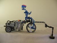
You might be able to use a differential instead of a clutch gear. I made a mechanism that did something similar a few years ago. -
Technic Geometry Help
Captainowie replied to aminnich's topic in LEGO Technic, Mindstorms, Model Team and Scale Modeling
Several different hexagons here http://www.brickshelf.com/cgi-bin/gallery.cgi?f=193780 -
Very well. Thanks for an enlightening discussion. Owen.
-
Yep, in my experience that's what happens when two intelligent people seem to not be able to agree on something! Ah, but this wasn't supposed to be an engineering problem, it was supposed to be an edge case to try to nail down a definition. If fixing the joints in place after the structure reaches equilibrium doesn't change the forces involved, would you still call the resulting structure a truss? If yes, then you could, in theory, construct a structure whose truss-ness depends on its load. This is neither a good nor a bad thing, just a consequence of the definition.
-
I very much doubt you'd find anyone on this forum willing to tell Blakbird to go away! Besides, this is a topic about truss design and we're talking about trusses. Ok, so assume we have two ideal (massless, rigid) members of unit length, pinned together (with massless pins). Their ends are securely fixed at the same height to immovable walls two units apart. The geometry of the situation allows that they will form a straight horizontal beam. Then we add the weight. In order to remain in equilibrium, there needs to be an upwards force to counter the weight of the weight. The members rotate slightly, so that the tension in the rods has a slight upwards component, and everything balances. But in order for that to happen, the distance between the ends of the rods must be less than the sum of the length of the rods. So either the rods deform (violating one assumption) or the walls move slightly inwards (violating another assumption). Or, I guess, the mass of the weight distorts spacetime enough that you can have a non-degenerate triangle with side lengths of 1, 1, 2. :-) This is doing my head in! In any case, I get that with the locked pin there's a bending force on what is now acting like one single member. Ok, so we unlock the pin again, and let the members rotate (the paragraph above notwithstanding!). Once they've reached equilibrium, there is nothing making the joint want to rotate. So we lock the pin again. How does that induce a bending moment? If you have a joint that could move but doesn't because its forces are balanced, how does preventing it from moving from that position all of a sudden make the forces unbalanced? (I recognise that my use of "balanced" and "unbalanced" here are probably not correct, but I hope you can still see what I'm getting at). Putting it another way, consider the two rods with a fixed joint in a v-shape, connected at the ends of the rods to the wall at the same height. I can imagine that if I pull down on the vertex that there will be some bending stress that will want to make the angle of the V become smaller. If I now move the walls a smidge closer together, I create a bending stress that wants to make the V angle wider. What happens when I pull on it now? The joint has a force that wants to make it wider, and a force that wants to make it narrower. Surely if I pull exactly hard enough, I can make those forces balance each other out, and there's no bending stress in the joint. Can you see why this is a reasonable (if ultimately futile) objection to your statements? I have made an attempt at drawing the freebody diagrams that should make it "obvious", but I don't know how to do that for an angled shape. I can see how they could be different, but what I can't get my head around is how a system can transition from one state to the other. Maybe there's something in the fact that I'm thinking about forces rather than stresses (I studied physics, not engineering!), but Wikipedia tells me that stress is just force per unit area, so I can't see how that would make a difference.
-
The thing that I really can't get past is this one: I completely accept that welding (or rusting) the pins in place change the forces that CAN act on the members, but I can't see how it necessarily DOES. If I have a true truss whose members are experiencing only compression or tension, and then I fix the joints in place, the members are still experiencing only compression or tension, aren't they? If there's no change to the external forces involved (what I meant above by "adding a load"), then since there's no acceleration there must also be no change to the internal forces involved, right? The only explanation I can think of is something that would require the joints to pivot - i.e. a (small) change in geometry. The only way I can see that happening is if we allow the members to deform with applied forces: members under tension get slightly longer, and members under compression get slightly shorter. But given that we're talking strict definitions and theories, I would have assumed ideal members (uniform density, completely inflexible, etc).