deejay Posted May 5, 2011 Hi there, your points motors look really good. Did you have to modify the switch so it would change with less friction? I had to do that with mine as the motors i use didn't have quite enough torque. Hi, thanks. :) Do you mean without modifiying the switchtracks? The Switchtracks must be a little modified because the Motors are not strong enough to switch with the plastic spring. Share this post Link to post Share on other sites
skaako Posted May 5, 2011 (edited) Hi, thanks. :) Do you mean without modifiying the switchtracks? The Switchtracks must be a little modified because the Motors are not strong enough to switch with the plastic spring. Hi, that's what i mean :) Yea i had the same problem with my design with trying to find a small enough motor with enough torque, the best way i found was just to remove the underneath of the switch and squeeze the friction part together with pliers. And the most readily available motor i could find was from a cdrom drive that controls the movement of the lens. In most drives i found this motor to be the same and took about 5 minutes to disassemble and remove. And these little motors are the perfect size to fit inside 2 stacked hollowed out 2 x 4 bricks :) Edited May 5, 2011 by skaako Share this post Link to post Share on other sites
deejay Posted August 16, 2011 Now, i tried a new Variant. The modify of the 7896 Lego Crosstrack. Each Track is electrical seperatly operated. It´s very tricky to modify, but i think it looks okay. :) http://www.youtube.com/watch?v=mIq081MEZnI Share this post Link to post Share on other sites
kyphur Posted October 7, 2011 If the problem with selling these commercially is basically that they are made of actual LEGO parts which have been modified then why not contact someone like ME-Models (who is already manufacturing LEGO compatible metal tracks) and seeing if they'd be interested it taking what you've got a further developing it into something that is commercially viable? If they built a housing that could snap onto LEGO plates then you eliminate LEGO having leverage in stopping the sales. Share this post Link to post Share on other sites
mr_jrt Posted October 7, 2011 If the problem with selling these commercially is basically that they are made of actual LEGO parts which have been modified then why not contact someone like ME-Models (who is already manufacturing LEGO compatible metal tracks) and seeing if they'd be interested it taking what you've got a further developing it into something that is commercially viable? If they built a housing that could snap onto LEGO plates then you eliminate LEGO having leverage in stopping the sales. ...or, you could just use the 3rd party clones stuff instead (i.e. Enlighten). Lego would have no say in that, surely? Share this post Link to post Share on other sites
kyphur Posted October 7, 2011 ...or, you could just use the 3rd party clones stuff instead (i.e. Enlighten). Lego would have no say in that, surely? Yes but I honestly would prefer it becomes something that is readily available to the "masses" (as in all of us Train fans who would want it) versus some guy in his garage hand-building them piece by piece... Share this post Link to post Share on other sites
skaako Posted October 8, 2011 (edited) Yes but I honestly would prefer it becomes something that is readily available to the "masses" (as in all of us Train fans who would want it) versus some guy in his garage hand-building them piece by piece... I'm not convinced that its commercially viable at this stage anyway, the biggest challenge being that the switching track still needs to be modified for it to work. And if you are willing to modify the track yourself, then you're probably more inclined to build the motors and housing by yourself too. And besides, its more fun to do Edited October 8, 2011 by skaako Share this post Link to post Share on other sites
deejay Posted December 12, 2011 Hey, i had time to make a new version of the Trackswitcher. :) Now it´s not necessary to modify the top of the Track. Only the Spring must be cutted in the bottom. http://www.youtube.com/watch?v=w2geeH20-fg Share this post Link to post Share on other sites
StephanSz Posted December 14, 2011 Wow, very good job! This looks like a professional remote switching solution. Share this post Link to post Share on other sites
kyphur Posted December 14, 2011 When you overcome the Spring issue please let me know... Share this post Link to post Share on other sites
JopieK Posted December 14, 2011 Now, i tried a new Variant. The modify of the 7896 Lego Crosstrack. Each Track is electrical seperatly operated. It´s very tricky to modify, but i think it looks okay. :) http://www.youtube.c...h?v=mIq081MEZnI Thanks deejay, did you overlook my question some days ago?! I'll post the link there too!!! Can you elaborate on how to modify the 7896 switch?!!! Update: Uh, it is 7996, not 7896!!! Share this post Link to post Share on other sites
deejay Posted December 15, 2011 Thanks deejay, did you overlook my question some days ago?! I'll post the link there too!!! Can you elaborate on how to modify the 7896 switch?!!! Update: Uh, it is 7996, not 7896!!! Hi Jopie, oh no i had not overlook. Sorry. I split the Plastic in two pieces an then i put a Plasticshift on it with glue. And then i made a Motorunit with 2 Micormotors. That´s it. Sorry for my English. Share this post Link to post Share on other sites
Tearloch Posted December 15, 2011 (edited) Hi Jopie, oh no i had not overlook. Sorry. I split the Plastic in two pieces an then i put a Plasticshift on it with glue. And then i made a Motorunit with 2 Micormotors. That´s it. Sorry for my English. Deejay: Amazing work. Could you post a picture or two showing how you did these modifications? I have been wanting to try this for a while, and was hoping to see some ideas on cutting the sliding bar and adding in the lever connections. The stock design has the yellow lever sitting in between 2 raised bars on the sliding piece. Once you split it, how did you add in the parts to allow your modified yellow levers to sit in between 2 raised bars? Also, when you split the sliding piece, did you have to shorten it at all, to allow for both sides to be in the position where their independant sliding piece is closest to the center (since the stock design does not allow this condition)? Edited December 15, 2011 by Tearloch Share this post Link to post Share on other sites
deejay Posted December 17, 2011 Deejay: Amazing work. Could you post a picture or two showing how you did these modifications? I have been wanting to try this for a while, and was hoping to see some ideas on cutting the sliding bar and adding in the lever connections. The stock design has the yellow lever sitting in between 2 raised bars on the sliding piece. Once you split it, how did you add in the parts to allow your modified yellow levers to sit in between 2 raised bars? Also, when you split the sliding piece, did you have to shorten it at all, to allow for both sides to be in the position where their independant sliding piece is closest to the center (since the stock design does not allow this condition)? Hi Tearloch. Sorry i can not create a gallery here. I get this failure code: [#1072] Sorry, but you do not have permission to use this feature. If you are not logged in, you may do so using the form below if available. And my global upload quote is used completely. I cut out the plastic at the sliding bar and put a new lever with glue on it. I send the admin an email why i can´t make a gallery. Maybe when it function i will load some Images up. Share this post Link to post Share on other sites
kyphur Posted December 17, 2011 Sorry i can not create a gallery here. I get this failure code: [#1072] Sorry, but you do not have permission to use this feature. How about using flickr to host your images and then just embedding them or linking to the set here? Share this post Link to post Share on other sites
deejay Posted December 27, 2011 How about using flickr to host your images and then just embedding them or linking to the set here? Now i put some Pictures on this Pdf: http://dj-marco-dee.de/Weichenumbau/Weichenumbauneu.pdf Share this post Link to post Share on other sites
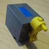
deejay Posted January 12, 2012 And now another Version. :) With colored Strings on the Side and not so high like the other Version. Share this post Link to post Share on other sites
deejay Posted February 27, 2012 And now a Set with the new 8 Motorunits. Share this post Link to post Share on other sites
deejay Posted April 1, 2012 And now a Controlldesk with 12 Actuators. Share this post Link to post Share on other sites
fluffybunny Posted August 30, 2012 (edited) Deejay, What gauge wire and connectors are you using especially on your new ones. On the control box it looks like female d-sub connectors, but on the remote switch boxes it looks like small female banana plugs on your new design. I have never seen anything like that and I am having trouble finding that. What connectors are you using for joining the control box to the remote switch boxes like the actual wire that would go around your layout? earler in the thread it looked like you were using male dsub connectors inside of a lego brick, is that what you are using? Edit: are you still using the motors from CD drives? the motor that controls the laser reader or have you found an online source for the motor? Thanks for your help and your design is great. Edited August 30, 2012 by fluffybunny Share this post Link to post Share on other sites
graphite Posted August 31, 2012 Does anyone have a torque wrench or gauge that could measure the torque required to flip the switch? Curious to find out what it takes. Share this post Link to post Share on other sites
deejay Posted September 7, 2012 Deejay, What gauge wire and connectors are you using especially on your new ones. On the control box it looks like female d-sub connectors, but on the remote switch boxes it looks like small female banana plugs on your new design. I have never seen anything like that and I am having trouble finding that. What connectors are you using for joining the control box to the remote switch boxes like the actual wire that would go around your layout? earler in the thread it looked like you were using male dsub connectors inside of a lego brick, is that what you are using? Edit: are you still using the motors from CD drives? the motor that controls the laser reader or have you found an online source for the motor? Thanks for your help and your design is great. HI fluffybunny, i think it´s a awg 22 wire gauge. First i used normal D-Sub connectorpins. Now i use bigger Connectorpins. The D-Subs were to fragile and it was to much work to put they into the Legobricks. No, i use these Motors still You can see the Cable in this Movie at 2:22 Min. These are the newest Versions. http://www.youtube.com/watch?v=h-AXPz2Cbgs Thanks for the Compliment. :) Share this post Link to post Share on other sites
Pulsar Posted September 15, 2012 Just when i decided i like 12v track over the new track because it has remote controlled switches, i find this... I guess the real question is: how much does it cost? :) Share this post Link to post Share on other sites
deejay Posted December 26, 2012 Now i have a Actuator who is not necessary to modify the Switchtrack. http://www.youtube.com/watch?v=7bJYKkbR_OM Share this post Link to post Share on other sites
King Aragorn Posted December 27, 2012 Very nice work even if I do not understand German well! Share this post Link to post Share on other sites