Victor Imaginator Posted December 29, 2017 Posted December 29, 2017 I read about virtual pivot steering in Sariel's blog a long time ago. He stated there that his solution can't be used with suspension. I decided that here's nothing impossible and develop so many prototypes that didn't worked) At 100th try i built something that finally work. It's not robust, it's not precise. But it have 2 studs travel and can steer) Weakest point it's lower ball joint of push rod. At maximum angle of steering to one side ball will pop out of 6L link instead of transfer force to springs. Any suggestions about improving this idea are welcome) Quote
Sariel Posted December 29, 2017 Posted December 29, 2017 Wow, that looks pretty close to real-life multi-link suspension! Quote
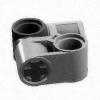
Myers Lego Technic Posted December 29, 2017 Posted December 29, 2017 (edited) I built something like that almost a year ago now. Good work though, a different approach. EDIT: I found an old pic of a primarily complete version. Edited December 29, 2017 by Myers Lego Technic Quote
Leonardo da Bricki Posted December 30, 2017 Posted December 30, 2017 Nice work! Shock placement seems odd to me, but hey, if it works, who cares? Quote
Boulderer Posted December 30, 2017 Posted December 30, 2017 This looks great, as has been said, close to the real world. One question, have you thought how you would build this into a vehicle and introduce the link to a steering wheel? Quote
nicjasno Posted December 30, 2017 Posted December 30, 2017 Cute as a proof of concept, but not really usable due to the excess amount of slack. Quote
Victor Imaginator Posted December 30, 2017 Author Posted December 30, 2017 Thanks for comments) @nicjasno I plan to improve it) It was surprising, but there's almost no slack in steering. Push-rods is largest problem now. @Boulderer Yes, i thinking about linkages. I think in final version there will be longitudinal steering rack. @Leonardo da Bricki It's almost same odd placement, as in 42000) @Myers Lego Technic, @Jurss I've tried many solutions, using 9L links looks compact and with 5 pins horizontal distance between ball joint inside wheel - whole system steer better, less slack. But my solution is far from best with that wobbling push-rod) @Sariel Nice to see you commenting thing, that was inspired by your construction long time ago) Quote
Aventador2004 Posted December 30, 2017 Posted December 30, 2017 Just now, Victor Imaginator said: @Sariel Nice to see you commenting thing, that was inspired by your construction long time ago) The Ferrari Testarossa? That popped up in my unread topics two days ago... Quote
nicjasno Posted December 30, 2017 Posted December 30, 2017 2 hours ago, Victor Imaginator said: @nicjasno I plan to improve it) It was surprising, but there's almost no slack in steering. Push-rods is largest problem now. Maybe not much left and right, but try twisting the hubs slightly and they go all over the place. The slack in ball joints is amazing. I tried this with the challenger suspension in one of my videos. Quote
Victor Imaginator Posted December 30, 2017 Author Posted December 30, 2017 13 minutes ago, nicjasno said: Maybe not much left and right, but try twisting the hubs slightly and they go all over the place. The slack in ball joints is amazing. I tried this with the challenger suspension in one of my videos. True) At least i don't plan to use this setup with driving wheels, so almost all twisting forces will rotate wheel instead of hub. Thanks for pointing at this problem anyway) But push-rod can twist hub against suspension arms, so push-rod is a problem. I need to solve it somehow. Quote
nicjasno Posted December 30, 2017 Posted December 30, 2017 That pushrod shows the slack. :) You could try relocating the pushrod ball 1 stud closer to the wheel by reengineering the yellow liftarm into something that can carry the ball pin. 2 #1 connectors with one of those new pinhole connectors with 1 stud axles on each side whould do the trick. Quote
DrJB Posted December 30, 2017 Posted December 30, 2017 Nicely done. The main issue with these (I think) is the excessive slack from all the links. Conceptually though, this is nice and as you've shown requires a wheel with enough clearance to house all the parts. Have you calculated what the 'scrub radius' is? It is the distance between the center of the tire's footprint and where the pivot axis intersects the ground. In real life, such scrub radius affects many performances of the vehicle, primarily handling and tire wear. Quote
Victor Imaginator Posted December 31, 2017 Author Posted December 31, 2017 @nicjasno There's 4 stud distance. #1 connectors will not work) I'll find how to fit ball joint deeper, but later. @DrJB Thanks. Scrub radius isn't zero. It was hard to measure, and i was lazy to calculate) But it can be changed almost without problems. Anyway i'll rebuild whole thing, when i find better push-rod position. As for wheel - i used standard wheel with thin tire, so any other tire will fit without problems. But Unimog/Claas tires can generate more slack. Quote
TheNextLegoDesinger Posted December 31, 2017 Posted December 31, 2017 ow that's funny, When I saw sariels' vid about it i thought the same, i did it way smaller though you can find the video of it on my youtube channel. though it wasn't that beautiful greets, TNLD PS sorry for my voice, i was still a little boy then Quote
Recommended Posts
Join the conversation
You can post now and register later. If you have an account, sign in now to post with your account.