
Mr Jos
-
Posts
515 -
Joined
-
Last visited
Content Type
Profiles
Forums
Gallery
Everything posted by Mr Jos
-
 The jerky motion comes from the program. Everything before 3:04 is me adjusting with PS4 controller to save some waypoints. Then it starts to run automatic between these points, this is much smoother, so start it at 3:04 to see the "real movement" you would also get with just sending it hard-coded waypoints and eliminate the PS4 teaching. Simply said; for example the end-effector is at position X= 200, Y=0, Z=350 with Yaw=0°, Pitch=0° and Roll=0°. This means the centerpoint is 200mm forward outside the center of the robot, on center axis (Y=0), and at 350mm high. The end-effector is pointing forward and flat. To move to lets say X=200, Y=100, Z=350 with yaw=0°, Pitch=0° and Roll=0° it has to move 100mm to the left. My program only takes these 2coordinates (waypoints can be hard-programmed or like in the video set with "X" button). The program then calculates the path to go in a straight line from "A" to "B", due to slow cycletimes with EV3 I had to set a limit to the amount of calculations to be done, first step is calculating a 6mm movement, send the motor and directly calculate next set of coordinates, then livecheck current motorpositions and send new speed for each motor. Around every 60-105ms a new speed is send to all motors, this makes it jerky. I could hard-program a set of coordinates with preset speeds to do some 'showing', and it would not be jerky as cycletimes would be way lower, but that was not my goal to be hardcoding a long time for 1 show run, when I can now make limitless amount of 'showruns' by teaching it with the PS4 controller just a few points, and let it do the calculating and adjusting on its own. Motors used are: EV3 Medium motor for Axis1 (Yaw the base) 1/11.666 gearing. Homing sensor = touch sensor at lower back side. EV3 Large motor for Axis2 (Pitch at base) with 1/42 gearing. Homing sensor = touch sensor at top of back side. EV3 Large motor for Axis3 (Pitch at arm) with 1/29.166 gearing. Homing sensor = touch sensor at the top of 1st arm, near the 3 medium motors. EV3 Medium motor for Axis4 (Roll whole wrist) with 1/5 gearing. Homing sensor = touch sensor at the roll turntable, this sensor allows this joint to turn around forever. EV3 Medium motor for Axis5 (Yaw the wrist) with 1/10 gearing. No homing sensor, the wrist gets jammed at its maximum position with low torque and stalling is detected for homing. EV3 Medium motor for Axis6 (Roll end-effector) with 1/7 gearing. Homing sensor = color sensor that looks for the red pin on the last turntable. All controlled by 2x EV3 brick connected with bluetooth with left side master, right side slave controlling base Yaw and end-effector Roll. Thanks, the programming took very long for my V1 project, once I had that I made it easy changeable by just changing motor directions for theta2 and theta3 and gearing with each 1 parameter to be changed for the whole program. The EV3 is not really made for these kind of robots, not having matrix calculations makes it so hard to make these straight lines without hard-coding, but I managed it! I did add some "subtitles", but they are in the timeline, you only see them next to the timestamp. I directly uploaded this raw video without any editing. But I do admit, someone who does not know what is behind it will not understand how hard work this little LEGO computer is delivering. Still need to see anyone else making straigth lines with full yaw/pitch/roll control possible with an EV3 without hard coding the path to follow.
 -
Generic Contest Discussion
Mr Jos replied to Jim's topic in LEGO Technic, Mindstorms, Model Team and Scale Modeling
I would like this very much. I'm a big fan of factory machines remade (stationary or moving), some of them just use 1 PF motor with some gearing to move so no need for expensive electronics, but it would be possible like robotics, warehouse systems, sorting machines (lego or candy, ..., size) mixing machines, household machines remade like mixers, washing machine, etcetc, so many possibilities but not much seen. I would vote for such contest instantly. -
6 DOF robotic arm by Jos
Mr Jos replied to Mr Jos's topic in LEGO Technic, Mindstorms, Model Team and Scale Modeling
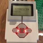
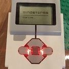
V2 of the 6DoF. Now more power and teaching with PS4 controller. -
https://rebrickable.com/mocs/MOC-76666/Mr_Jos/6-degrees-of-freedom-6dof-fully-automatic-robotic-arm-with-inverse-kinematics-programmed/#details EDIT: Last video made shown here; /EDIT My V1, 6 degrees of freedom robot worked, but had no power to lift anything when fully stretched. I designed a complete new base and managed to even make it slimmer at the base, and a longer arm allowing it to move closer to itself. Gearing changed from 1/10 to 1/42 at the base. PS4 controller used to teach the robot new waypoints, it then move in a straight line to each point (live calculating on the EV3 brick to compensate for stress in the gears). Except the PS4 controller, everything is original LEGO, it does work without it by just running a saved waypoint program. All cables are original ones, unlike in my other project seen at the back (highbay warehouse crane that needed 50cm+ cables I made myself). Need to modify some parts of the robot for more durability, then I will try to make instructions for it when I'm happy with it. When I'm finished with this robot I'm planning to make many more industrial "machines" that are not made before in LEGO (or not many times), it will now be easier as I expanded my LBG beams and connectors in storage. EDIT: Photo's added; EDIT: For geeks only;
-
If you have just that set you can see the first link I posted in my previous post, You have to scroll down to see the alternative builds and then click on one of them to see the detailed information about them. https://rebrickable.com/sets/31313-1/mindstorms-ev3/#alt_builds There are some plotters, drawing machines etc. Some instructions are free and have the program aswell, try to look at them for inspiration, but don't go for a 100% copy offcourse as it's still a school project to show what he can do.
-
What EV3 kit do you have? The education (comes with rechargeable battery) or the home edition? They have different sensors so it would be good to know what you have. Also do you have any additional Lego/other sets that can be used for parts to make the project? Some suggestions for base kits only; Home Edition: https://rebrickable.com/sets/31313-1/mindstorms-ev3/#alt_builds Educational Edition: https://rebrickable.com/sets/45544-1/ev3-core-set/#alt_builds Industry/Factory examples; With more parts and only 1 EV3 brick you can make some kind of warehouse crane, you need to have a different supply then in my video (like small bricks coming to start position by gravity, take them with the crane/robot arm and drop them off on a set/random position), but this video is just to show a industry example (the crane uses 1 brick, the conveyors 2bricks). Another industry project using 1 brick and few 'normal motors remote controlled' to represent a sheet metal perforating machine. If your son has some extra parts and good imagination he could try to think about any industrial machine and try to make it. First point is how many motors do I have, and how many do I need for what I want to make, if more are needed, find something different or simplify the working.
-
6 DOF robotic arm by Jos
Mr Jos replied to Mr Jos's topic in LEGO Technic, Mindstorms, Model Team and Scale Modeling
The deviation was from me being impatient to upload a video. The zero-ing I use for theta1 is still the same as months ago, and that was never checked if it actually is correct, it was on sight done and it's off by a few degrees as I also changed the support under joint 1, the homing isn't 0°. Maybe it's better I look to control it sooner then later haha. If you take in mind that theta1 is a little shifted it is a nice square. Thanks for your comments and feedback, next thing will be to try control it with a BT remote, need to look at what is possible. So I can jog the robot to certain points and save them to perform several tasks without having to hardcode the positions/pitch/yaw/roll. But as I'm far away from home I don't know when that will be. EDIT: I did find the correct value for positioning theta1. It was off by 22motor degrees (4200 for full rot = 2°) Now redid the square around base and it's waaay better. -
@all of you: Wanted to let you know that it is possible with Micropython/Pybricks to perform Inverse Kinematics on the 6DoF!! Just finished being able to do all kinds of positioning, but it's not 100% finished yet, need to clean up my code a lot and build in some limits (now only theta2/3/5 are limited, but it can still crash into itselve. if Yaw >120° and XYZ gets to close to the robot. This is what I used for this video. Now I want to find out if and how I can use a bluetooth controller together with the 6DoF. I think like Playstation or something? I don't have any consoles. But what I want to do is move X/Y with joystick whilst maintaining Z altitude, that gets controlled by other buttons. 2nd joystick for Yaw/Pitch and buttons for Roll. Then use a button to save positions (with the forward kinematics), and then let the program run. But not tracking exactly what was done with remote, but using a linear path with IK. So it will be easy to make animations, and fun I guess? Without having to hardcode these positions like in the screenshot.
-
Multiple EV3 control in Pybricks
Mr Jos replied to Jonas's topic in LEGO Technic, Mindstorms, Model Team and Scale Modeling
When you build your new one, try putting at least 2 gears on each joint. The backlash will get smaller by just having 2, and if needed you can put the 2nd gear 1 teeth further, making the joint under tension and having no backlash at all. That is, if you put good bracing that it can not skip gears to release the tension. It is what I do on my theta1, 2gears with small tension. Have fun rebuilding it! In my opinion it always gets better when I rebuild the same kind of machines, as you know the shortcomings of the previous. -
6 DOF robotic arm by Jos
Mr Jos replied to Mr Jos's topic in LEGO Technic, Mindstorms, Model Team and Scale Modeling
Not perfect, but now it's only looking to optimize it as much as possible to try smooth it out more. Now we know 6DoF IK is possible with Pybricks! -
6 DOF robotic arm by Jos
Mr Jos replied to Mr Jos's topic in LEGO Technic, Mindstorms, Model Team and Scale Modeling
Quick update: It's alive! Roll/pitch/yaw of end-effector is fully functioning. I can make it take any stance, and fluidly transition to the next stance whilst moving to new X/Y/Z coordinates. Only thing is that it sometimes does a 360° on the θ6 whilst unwanted, need to look how I can solve that, but the biggest part is finished. Thought it would never be possible with Micropython. I also need to change the path finding as it takes XYZnew - XYZold and moves 6mm at a time to the largest of those 3 distances. But now that I can roll/pitch/yaw around 1 XYZ point I need to look into moving certain ° at a time if the XYZ distance is to small (or 0). Once that all is finished I will take another video and those who want to make their own 6DoF move with IK can try to see in my messy program how I did it. To do: - Remove unwanted 360° turns on θ1, θ4 and θ6. - Change pathfinding for short distances, but high roll/pitch/yaw change. - Cleanup program. - Make a video EDIT: 360° Unwanted solved! -
6 DOF robotic arm by Jos
Mr Jos replied to Mr Jos's topic in LEGO Technic, Mindstorms, Model Team and Scale Modeling
I'm pretty sure I just found the answer for θ5. For every case using any [Roll, Pitch, Yaw] matching any angles [θ1, θ32] that I tried it seems a logical result for me. After θ1, θ2, θ3 that are easy, θ5 is actually just a very short but easy calculation with no need of an equation, but if you don't have any documentation like me it's tough. Tomorrow I start searching θ4 and maybe θ6. If I do find it I will clean up my program a bit and show to those who are interested, or just give some hints how to do it. Here is what I got so far, color code is in the screenshot. Edit: θ4 and θ5 seem to be working good now with pitch in a few tests (but without yaw/roll mixed) as my θ6 is still not good for pitch, I get Math Domain error whilst I did not expect it.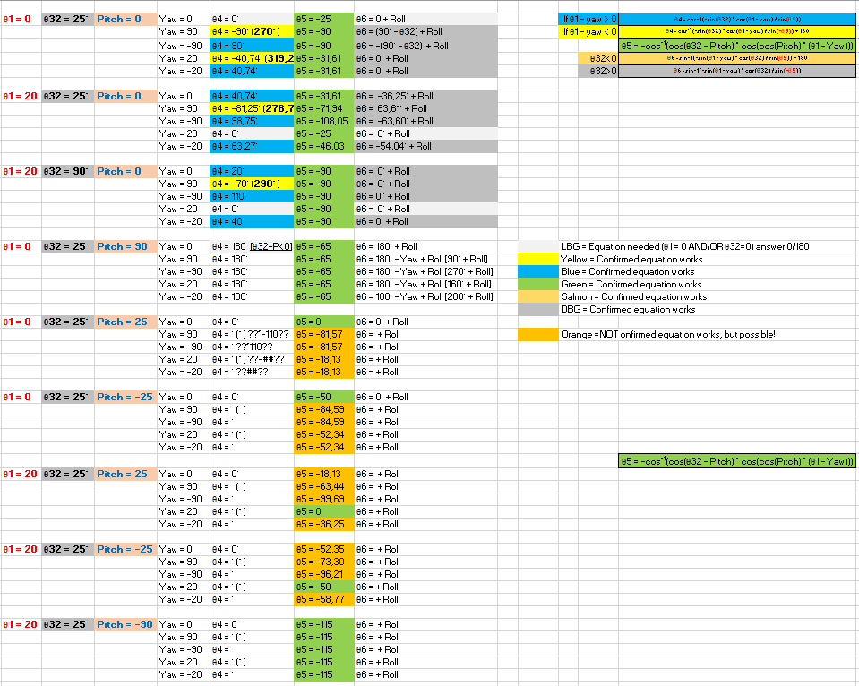
-
6 DOF robotic arm by Jos
Mr Jos replied to Mr Jos's topic in LEGO Technic, Mindstorms, Model Team and Scale Modeling
Thanks, I have been writing down all kind of possibilities for combinations of positive for this, negative of other, but smaller or bigger, etcetc and then tried finding calculations that work. And each time track back to see if it still works for other components. This is/was very time consuming finding the correct equations to eliminate the multiple solutions like for θ6; (Carefull this is not correct yet, still trying to find solution working for pitch) if theta32 - pitch > 0: theta6 = math.degrees(math.asin(-math.cos(math.radians(theta32 - pitch)) * math.sin(math.radians(theta1 - math.fmod(yaw, 360))) / math.sin(math.radians(-theta5)))) + roll elif theta32 - pitch < 0: theta6 = math.degrees(math.asin(-math.cos(math.radians(theta32 - pitch)) * math.sin(math.radians(theta1 - math.fmod(yaw, 360))) / math.sin(math.radians(theta5)))) + 180 + roll elif theta1 - math.fmod(yaw, 360) < 0: if math.fmod(yaw, 360) == 0: theta6 = 270 + roll elif math.fmod(yaw, 360) != 0: theta6 = 90 + roll elif theta1 - math.fmod(yaw, 360) > 0: if math.fmod(yaw, 360) == 0: theta6 = 90 + roll elif math.fmod(yaw, 360) != 0: theta6 = 270 + roll So there's already 6 possibilities for my θ6, but it will only choose the one fitting current 'stance' of the robot. Just picking one will make the joints go nuts and do random 180° turns. After the video I had to change a bit of code to allow unlimited turns for θ1, it works as long as pitch stays within 360°, might have to take a look at it after I finish the pitch. I did have LOADS of time, and it was needed to program the IK, as I'm in a quarantaine hotel for 15nights (you can see it in the video). And can't leave my room for 1minute. 3days left now... tic tac... -
Really good job done with the pneumatics. Makes it look way more realistic then the motor-actuator driven buckets. Hope Lego will release some more pneumatic models to give us more parts for a better price.
-
6 DOF robotic arm by Jos
Mr Jos replied to Mr Jos's topic in LEGO Technic, Mindstorms, Model Team and Scale Modeling
And here is the promised video, For the people who want to know how I'm doing the IK so far in the program (Don't have pitch yet), I show it in the second half of the video. Full control to make the end-effector go to a X/Y/Z position, now the input is a hard-coded list of end-positions (no lists are used to know the angles for every position, it gets calculated), but you can use anything if you want, remote control to add extra X or Y or Z or all together. Meanwhile it can change the end-effector's Roll and Yaw (Roll not shown in video so it's easy to see the fork stays firmly upright, but Roll is easy, just add Theta6 = Theta6 + Roll. As it's not affecting the position. In the video I also show the code for this robot, remember, I started from 0. I did not use any code from someone else, and I started programming just few months ago for the first time. So it's maybe a mess and some things to long. Feel free to give feedback how to make it 'faster' (meaning lower looptime = can make steps smaller than 6mm). -
6 DOF robotic arm by Jos
Mr Jos replied to Mr Jos's topic in LEGO Technic, Mindstorms, Model Team and Scale Modeling
Just had my first Yaw adjustment working, Roll also works well. It kept the fork flat and making a 90° turn whilst going to the new X/Y/Z point. Will do some more testing, and if all work correct I might make a new video. If so then I only need to add in pitch (not needed for a robot acting as forklift as it should always stay flat as it is now. The looptime did not increase much with the yaw movement added, still within 52-89ms to find new thetas and corresponding speed values for those joints. -
6 DOF robotic arm by Jos
Mr Jos replied to Mr Jos's topic in LEGO Technic, Mindstorms, Model Team and Scale Modeling
Thanks, These motors do need some gearing down indeed to be accurate and powerfull enough. And I've seen in a video that the power from the RI motors is lower then the EV3 Large motors so it would need even more gearing down pitch_base_full_rot = 3600 # 360 / 12 * 60 / 12 * 24 pitch_arm_full_rot = 4500 # 360 / 12 * 60 / 12 * 24 / 16 * 20 roll_arm_full_rot = 1800 # 360 / 12 * 60 / 16 * 16 / 16 * 16 yaw_arm_full_rot = 3600 # 360 / 12 * 60 / 12 * 12 / 16 * 16 / 12 * 24 roll_head_full_rot = 2520 # 360 / 8 * 56 / 12 * 12 / 4 * 4 yaw_base_full_rot = 4200 # 360 / 12 *140 / 12 * 12 That's the gearing I'm running now. If I would start again with this robot I would gear down the base pitch more, as now it's sometimes not strong enough when fully extended. 3600 means it needs 10 full rotations of the motor to turn the joint 1 rotation, or 1motor degree turning = 0,1° on the robot. -
6 DOF robotic arm by Jos
Mr Jos replied to Mr Jos's topic in LEGO Technic, Mindstorms, Model Team and Scale Modeling
I programmed it so that it pulls the current X/Y/Z position from the forward kinematics, then with the new coordinates it knows how far it should move the end-effector in X/Y/Z. I pull out the largest of the 3 and make it move 6mm at a time closer to the new position. As I know howmany steps of 6mm I will need to get there I divide the other 2 coordinates in equal steps and move a 'step'. This is calculated quickly and each position is send to the move subroutine, by calculating the time needed to arrive at the given position I know when to send the next position. By finetuning this I managed to make it move smoother so it does not jerk incase it stops at each position. θ1, θ2 and θ3 are no problem at all, even with a roll/pitch/yaw trim. But θ4, θ5 and θ6 now only are calculated correctly if end-effector is at 0° roll/pitch/yaw. At this moment trying to find out what I need to change in the code for a 90° yaw move and if all positions in between will be correct. As testing used up much time homing all joints I tried speeding it up, and it seems to stay relativly stable so far. If I find anything more for the IK I will post it here. -
[MOC] Audi RS6 Avant
Mr Jos replied to 2GodBDGlory's topic in LEGO Technic, Mindstorms, Model Team and Scale Modeling
That's a lot of functionality in a small car! I see you even put a driven shaft through the base of a pneumatic cylinder to mount it. Now I wonder what your friend build so we can choose who wins! -
6 DOF robotic arm by Jos
Mr Jos replied to Mr Jos's topic in LEGO Technic, Mindstorms, Model Team and Scale Modeling
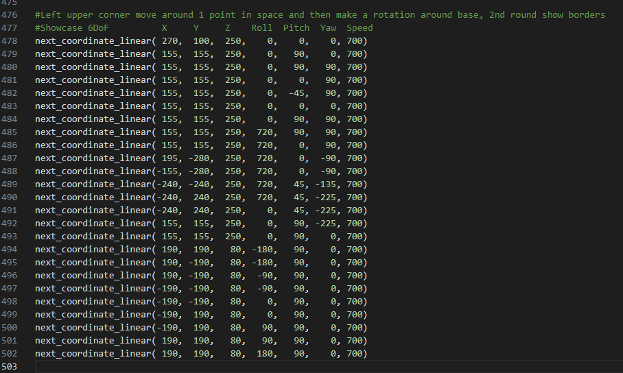
Finally an update in the controlling of the 6DoF. The only input for moving in a straigth line from current position to new position, XYZ is in millimeters from center of robot and floor level = (Xnew, Ynew, Znew, Roll, Pitch, Yaw, Maxspeed) while True: next_coordinate(160, 200, 380, 0, 0, 0, 500) next_coordinate(160, 200, 140, 0, 0, 0, 500) next_coordinate(360, 0, 140, 0, 0, 0, 500) next_coordinate(160, -200, 140, 0, 0, 0, 500) next_coordinate(160, -200, 380, 0, 0, 0, 500) next_coordinate(300, 0, 200, 0, 0, 0, 500) next_coordinate(160, -200, 380, 0, 0, 0, 500) I finally made a working code to do basic inverse kinematics. I need to test and make it better/be able to do more. For now it will work for in θ1 = [90° -> -90°] (as it keeps the end effector always pointing in the same direction as roll/pitch/yaw needs to be 0). θ1, θ2 and θ3 are calculated by finding the wrist X/Y/Z. Then θ4, θ5 and θ6 are calculated to keep the end effector in same direction and flat. The movement is already smoother now than in this video as I changed some parameters and it doesn't drift so far anymore. Now I want to try adding Yaw to the end effector (keep it flat but turn around) so I can use the full 360° of θ1. Note that it already uses full 360°+ rotation on θ4 and θ6 when it keeps making rotations around. -
You might want to try putting the sensors on an angle, now they point 90° (Downwards). Try mounting them from behind the tip of flipper watching to the top of the board, and point down only around 30° not 90°. This way the measured distance will be larger, less error readings will occur. I would like to make a test-setup to show/test but I'm 3months away from home (pile of Lego), only got my 6DoF with me. If needed I can make a sketch on paper and upload it. Got time enough sitting out 15days quarantaine not allowed to leave the hotel for 1minute.
-
Try using www.Flickr.com, then upload your photo's, and copy the link to them here.
-
Can't you just downgear or even use a worm gear to get the slow speed needed? It will have way more torque and still turn slowly than lowering voltage/PWM.
-
Hey, I don't see any of the pictures? Have you posted the correct link for them?
-
I made it to calculate current X/Y/Z positions of the end-effector for my 6DoF, with lengths a1, a2, etc as arm length variables so it fits any robot arm. And it works good. Problem is, I gave up with reverse kinematics. I got to the point I know how to do it, and I get theta1+2+3 with triangular math, but for theta4+5 and 6 there is no other way then calculating the inverted 3x3 matrix where theta1/2/3 are variables in and thereafter multiply it with 3x3 matrix with desired end effector pitch/yaw/roll/position. Micropython has no option to calculate this inversion, problem is that it's no simple calculation. I tried a long time finding a workaround with some if statements for a given theta2+3 and using all kinds of math with cos/sin but there is no linearity in the math for theta4/5/6. So if you find a way to calculate 3x3 matrix inversion and multiplication I will be happy to give you my calculations how you can do it.