
SNIPE
-
Posts
2,678 -
Joined
-
Last visited
Content Type
Profiles
Forums
Gallery
Everything posted by SNIPE
-
hi when i tried to use the 1 piece diff case that i do not have in real life in LDD the gears fitted in fine but when i make the next closest thing by using two 4 stud, 3 hole beams in parallel and filling in the side gaps to make it a square the same dimensions as the original case the three gears fitted with the case but the 4th did not so it must have stuck out, when i did this in LDD (using these same multiple pieces for the diff it fitted fine though so do the gears below fit in the case below and rotate fine? and also do these gears work in the case http://www.bricklink.com/catalogItem.asp?P=4143 here is the case i used first: (one piece) http://www.bricklink.com/catalogItem.asp?P=32324 the gears i used originally are these: http://www.bricklink.com/catalogItem.asp?P=6589
-
lego supercar update
SNIPE replied to SNIPE's topic in LEGO Technic, Mindstorms, Model Team and Scale Modeling
about the same wodth as the 8448 or mayse bigger i am using verticsl suspention which works differently, theres no suspention yet thr tyres and wheels look normal enough -
lego supercar update
SNIPE posted a topic in LEGO Technic, Mindstorms, Model Team and Scale Modeling
i have the front done and it looks great and works fine, its the seem on the back but the two holes that line up are connected to stop the back wheels tilting as if it was steering (like on the front) the parts i am still going to get is mostly everything because of the colors i want, i built an LDD mode and a real mode using any color the correct part happened to be. here is some pictures of it so far, the ball joints and ball cup beams (which are connected to the gear rack and control the turning of the car (a.k.a. wheels)) are not there and a couple of other parts are not there such as the black frictioned kingpins that go through the wishbones, the 62x62 silver rims and the LEGO Michigan tires that go with the rims , the disk brakes and the calipers, the caliper mounts and pins the disk brake spacer plate,the inner Tyre strengtheners, the wheel quick release handle and probably something else, and some of these parts such as the wheels are replaced with something similar) 1 http://i52.tinypic.com/2hwhgkl.jpg 2 http://i56.tinypic.com/idfv2s.jpg 3 http://i54.tinypic.com/2hf2qmx.jpg 4 http://i54.tinypic.com/2db2ano.jpg 5 http://i56.tinypic.com/2v3k8zd.jpg 6 http://i55.tinypic.com/t5mzw0.jpg 7 http://i52.tinypic.com/30uzcc9.jpg 8 http://i55.tinypic.com/20gkx3o.jpg 9 http://i52.tinypic.com/16lya7p.jpg 10 http://i56.tinypic.com/mm65oi.jpg 11 http://i56.tinypic.com/zunu6f.jpg 12 http://i56.tinypic.com/dbljd5.jpg 13 http://i55.tinypic.com/117aesw.jpg 14 http://i55.tinypic.com/213m6mg.jpg 15 http://i52.tinypic.com/qn21ch.jpg last http://i52.tinypic.com/2mfn3av.jpg also the engine is not a flat 10 its two flat 8's (one is front mounted, other is ream mounted) the flat 10 was just to experiment with so i can get the design correct before making a couple of flat 8's coming next: suspension, steering rack and arms, gearbox (i can only show pics if i have an applicable amount of similar parts to make a prototype type with, until i get the exact parts online i will have to show LDD screen shots and prototypes of applicable parts of the supercar. -
hi, does anybody have / know where i can find a LDD model file of either the silver champion, the Williams f1 car or the LEGO 8674 f1 that i can get a copy of? i just need the rear part (wishbones, wheels, tires, differential, and suspension) but when i try and make it in LDD i would have to make other parts of the model in order for them to fit etc and it would be very confusing trying to make it by leaving out these other parts. *note* i built the rear wishbone spindle and wheel Assembly for the rear right wheel and modified it to make it stronger but i don't have many parts that i need the front will be strengthened too but i need a way to pass the added universal joints through the pivot axle and connect that to the the front differential, the steering is out of the way so that shouldn't be a problem and the suspension is already there and should not get in the way.
-
engine placement
SNIPE replied to SNIPE's topic in LEGO Technic, Mindstorms, Model Team and Scale Modeling
my gearbox can control both engines interdependently so i don't think having 2 gearboxes is necessary imagine having 1 engine in 1st gear and the other in second gear well my gearbox can do this because of the splitter control which lets the axles that come out of both ends of the gearbox and join into the two differentials spin independently (at different speeds) also the gears don't actually do much in my model as they are the same size (like on the other Lego supercars like the 8448) this is basicaly how a variable center differential works because the faster the engine and wheels spin the more power is outputted if the VCD is set to a high power output limit of say 50% to the front wheels and 50% to the back -
engine placement
SNIPE replied to SNIPE's topic in LEGO Technic, Mindstorms, Model Team and Scale Modeling
ive seen an audi TT with 2 v6 engines one at the front and one at the back -
engine placement
SNIPE replied to SNIPE's topic in LEGO Technic, Mindstorms, Model Team and Scale Modeling
front axle + differential -> front engine -> gearbox -> rear engine -> rear axle + differential it could also be powered oppositley since its 4 wheel drive so front axle + differential <- front engine <- gearbox <- rear engine <- rear axle + differential or independently front axle + differential <- front engine <- gearbox -> rear engine -> rear axle + differential the front set of parts can drive the rear set and vice versa and if i select the gear which disconnects the 4wheel drive they can be independent. -
engine placement
SNIPE replied to SNIPE's topic in LEGO Technic, Mindstorms, Model Team and Scale Modeling
i was thinking having the gearbox in the middle and a v8 either side , is this a good idea? -
which would be better for weight distribution and delivering the power a mid mounted w16 OR front mounted v8 and rear mounted v8
-
maybe i should try cleaning my bricks but then again i like them dulled aswell
-
ok ill make a new block
-
the way i did it was simular to this exept i used the dark grey technik 3 axle with stop and the piston fitted over the stop the piston did not tilt much so ill try the new idea like on that motorbike. as the.ball joints will let the pistons tilt more which could prevent the jamming if this does not work, i will need more ideas on custom mechanisms
-
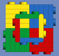
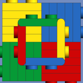
any ideas on making some mechanisms for the bottom block (mechanism as in pistons, conrods, cranks and crankshaft)
-
sorry i forgot to upload the pics http://oi55.tinypic.com/2ngyk9k.jpg http://oi56.tinypic.com/xo4f9j.jpg
-
Hi, i made a W16 engine by mounting 2 flat 8 engines on top of one another but the bottom engine is wider as the 2 blocks are spaces side apart more so the top flat 8 can sit in it to save height. (see images) i can get the top flat 8 working fine but when i tried to use either normal technic con-rods and cranks or my own custom made con-rods and cranks the thing jammed, i needed custom con-rods and cranks because the technic ones are too short for the gap between the bottom 1 blocks also im not sure but i think the custom conrods also got stuck on the outer rim of the block port/hole since the con-rods move up and down on a pivot a little. i also tried the technic ones with 2 crank shafts on the bottom but they got stopped by the obstructing top block I've tried using the different holes in the girders on the front and back of the engine but no luck so i need some ideas of
-
disk brakes
SNIPE replied to SNIPE's topic in LEGO Technic, Mindstorms, Model Team and Scale Modeling
probably not i think ill use the silver technik disks 2 posts above unless there is something slightly taller but still sleek looking also is there some disk that i can use to put over the middle bit of the inside of the rim (rim image at top of page)?, it would require having a larger hole in the centre -
yes, i would like to do it that way, i can just make 2 rear units and make one so the wheels can turn since i need 4 wheel drive i will see which mech is better out of the silver champion, the williams f1 car or the ferrari f1 1:8 car (the one with suspension) how would i go about getting all wheel drive? i have a diff i made myself that has 6 internal gears and can have another 2 outer gears (the 6 gears are housed) that i can use for the front and back
-
disk brakes
SNIPE replied to SNIPE's topic in LEGO Technic, Mindstorms, Model Team and Scale Modeling
ive tried them both and there too smsll -
hi what round thing can i use to replecate a disk brake i need a disk that is big and not really wide to go in the technik williams f1 car rims
-
i dont get that statement, 'not feasible' means its not a good idea but then you said i would have more shocks availible etc if i did this, so will i do it or not? i attached a few shocks to the wishbones, some worked ,some did not but even if they did work the wishbones were moving up when compressed which means the floor etc hitting off the ground i moved it by hand so that the wishbones were diagonally angled so there was a gap and flipped the assembly upside down so the wishbones went up when it hit a bump but the spindle was diagonal therefore so would the wheel be, and also the shock was compressed when it was in the normal position (like on a flat surface) i tried making a custom which without a spring, it worked great but still the wishbones were moving wrongly. so i was thinking about using a similar idea here but modifying the assembly so there is a diff on the front and back and still have steering on the front the model in the link has all 4 wheel suspension. and i can try and modify it again , but making it stronger this way is like you were saying i think.
-
whats the smallest lego axle you can get get that has threads on it? i could use the threads to adjust the spring rate.
-
i was actually thinking the same thing too , i have the cymenders from the lego city green dump truck set, id need to buy a lego spring from a lego shock assembly (just the spring), any ideas where i can find one? the air would escape from the parts shown and so would fluid so it will have to be mechanical (as in spring)
-
the first image the. shock is too short and the ssecond image is too wide and i havmt tried the third image yet because the one in LDD is compresed and therefore too short
-
i was designing in LEGO digital designer before buying the parts and building it in real life and it was going well but now i have problems the suspension i originally used was a linear actuator but since this is so long wide and tall i have to mount it from the top wishbone mount to the frame next the diff (the wishbones are half the length of this actuator after doing that i knew there would be no pivot point of compression ,so the shock will never compress so i added diagonal mounts which went back into the corner of the bottom wishbone but that that would not do anything either so the shock wouldn't work i then tried to typically mount the shock diagonally (from bottom wishbone to top wishbone or from one wishbone to a mount so the shock compresses but the actuator didn't fit and the other ones were too short, can somebody give me an image of a shock that would fit (i need room for the axle to go through also since its an AWD (all wheel drive) vehicle unless i mount the shock outside of the wishbones instead of inside of the gap area of them.
-
when i built the 8448 and added a v14 engine and 4 pull back motors and 1 electric motor i smashed a lot of gears in the diff, and the car kept on crumbling so yes you can have too much torque