
Hod Carrier
-
Posts
1,007 -
Joined
-
Last visited
Content Type
Profiles
Forums
Gallery
Everything posted by Hod Carrier
-
As we're all grounded at the moment, I thought I'd use some of the time to have a little look at ways to make subtle improvements to the track. It's always great to debut a new loco or item of rolling stock but, apart from ballasting, the track on which these trains run often gets overlooked. As a train driver here in the UK I thought I'd see how to add the sort of details seen along the lineside in order to add realism, often with only a few parts. These digital designs represent details found on modern British railway lines, and as such, I appreciate that the precise designs will have only minor appeal, but I hope that it will serve as an inspiration to designers to look more closely at the infrastructure and to consider adding similar details to their builds. All of the designs are compatible with the PennLUG standard of track ballasting. This is quite a busy scene showing a typical modern British railway signal and it's associated infrastructure. As well as the signal itself, included are the signalling equipment cabinets, TPWS train-stop loops, signalpost telephone and cable troughs. The signal is a modern lightweight signal based on a flat panel design containing LEDs to show each of the three colour aspects. These are becoming increasingly common in the UK as older signalling is renewed. The smaller black tile represents the signal identification plate. Also shown is the signalpost telephone. In the past these phones would have been mounted directly onto the signalpost itself, but the modern standard is to have them separate with a walkway and handrail for protection. A selection of lineside equipment cabinets together with the concrete cable troughs. These troughs can vary in colour depending on age and weathering. They are also rarely dead straight or level and can often disappear altogether under piles of ballast or vegetation, which gives the modeller licence to do more interesting things with them. On routes with more than one line the troughs and cabinets can appear either on both sides or just on one side. This is the Automatic Warning System (AWS) track equipment used in conjunction with a signal. Using magnets and electro-magnets, this operates the in-cab equipment and indicates to the driver whether the signal is clear or at caution. These are generally accompanied by a small equipment cabinet. The grey slope at the front of the magnet is there to protect it from anything hanging from the train and is why these installations are referred to as "AWS ramps". This is the typical arrangement used on uni-directional lines, but there are other AWS arrangements for bi-directional lines as well as fixed magnets to alert drivers to lineside warning signs, for example. The correct operation of the signals relies on train detection. Previously this was done using track circuits, but modern signalling schemes now use axle counters. This is an axle counter head unit with it's associated lineside box. The parts for these do stand about half a plate above the rail, but there are no clearance issues for trains using LEGO's train motor. Another common feature now seen on the UK network is Train Protection and Warning System (TPWS). This is a radio-based safety system that will automatically stop a train under certain circumstances. The system uses an arming loop and a trigger loop and can be set to trigger the train's brake by varying the distance between the two loops. The parts required for these are very simple and few in number. TPWS comes in two forms; overspeed and train-stop. The pair of loops placed end to end (left) is the train-stop arrangement and is used at signals to stop a train if the signal is passed when it's red. The loops spaced apart (right) are the overspeed arrangement. These might be used where a reduction in speed needs to be enforced for safety, such as on approach to a speed restriction or approaching a red signal. These humble looking things are treadles. They are basically switches on the track which are operated by the train wheels and can be used either singly or in pairs to operate things like footpath crossing warning lights or even some automatic road crossings. Not much to add with this photo. Treadles are placed both before and after the equipment they are intended to control; once to activate it and once to deactivate it once the train has passed. Sometimes it's necessary for cables to cross underneath the track from one side to the other. To achieve this safely, plastic pipes are laid between the sleepers to carry the cables. The colours normally used are contrasting such as orange or blue, but they quickly weather to a duller shade.
-
[MOC] 1:48 Southern Railway / Bulleid Leader
Hod Carrier replied to Commander Wolf's topic in LEGO Train Tech
Oops!! You have a swept kinematic envelope issue there. Glad to see the updates on the old girl. You've got her running very sweetly. The R40 issue is something that I think you might have to let go of if your trains are even anywhere close to scale. -
Lego acquiring Bricklink - Problem with 3D-printed parts?
Hod Carrier replied to ScotNick's topic in LEGO Train Tech
LEGO's stance may indeed be more nuanced than Ms Goldin's answers suggest, and have no doubt that LEGO have real reasons for wanting to avoid depictions of violence or warfare, but I don't buy the line of reasoning that you outline. The usual line of argument against representations of violence in the toy market is the desire to avoid normalising violence in the lives of young people and children by avoiding violent elements in children's play, and this is a laudable and wholly defensible position with which I have no issue. Where I find LEGO's position to be hypocritical is the distinction it seems to be drawing between historical or fantasy violence and warfare and real or recent violence and warfare, where one is OK but the other is not. The Star Wars film franchise clearly champions a highly moralistic message where good always triumphs over evil, even when greatly outnumbered, and the baddie gets his comeuppance (usually killed). But this triumph usually comes as the result of a show of force where one side engages the other in violent warfare with a horrific body count, although this outcome is usually not shown. LEGO clearly has no issue with this and is happy to enthusiastically support the theme. The little cynical voice at the back of my head would say that this is because it nets them an enormous pile of cash whereas BrickArms selling custom parts through Bricklink is only going to earn them tuppence ha'penny and is, therefore, an easy target. Now I will concede that fantasy warfare is easier to frame in terms of it's morality where real warfare is clearly morally ambiguous, but in what other way is fantasy warfare different from real warfare in terms of introducing elements of violence into children's play and what effect does this have on them? I have previously been involved with a project that sent shoeboxes containing gifts to children in developing nations at Christmas, and the policy there was that nothing related to warfare or violence was permitted whatsoever, including fantasy themes. Lets be clear. None of this is going to affect AFOLs nor, as has been said, the availability of custom parts through one portal or another, and neither is it going to change my own buying or building habits nor my enthusiasm as an AFOL. What rankles is the inconsistency in the application of and the justification behind the policy. -
Lego acquiring Bricklink - Problem with 3D-printed parts?
Hod Carrier replied to ScotNick's topic in LEGO Train Tech
I don’t think anyone else has used the word, but I shall. If LEGO is going to ban BrickArms custom items from Bricklink due to the association with warfare and violence, such action would be hypocritical. You cannot champion themes that are, by definition, violent and simultaneously take the moral high ground on violence. Heck, one of their most lucrative themes even contains the word “wars” in its title. The bogie sideframe parts I’ve used for my 4-wide models are genuine LEGO parts and, you guessed it, are guns. I’m hopeful that this stupid double-standard nonsense that they’re aiming at BrickArms won’t necessarily applying for other third party parts suppliers. If they’re going to honour Dan Jezek’s original vision I would hope that they will leave space for non-LEGO LEGO compatible parts, as at least the current iteration of Bricklink has a specific heading for custom parts. -
Oh dear, this is starting to get a lot more complicated than I imagined. I appreciate the suggestion to use the EV3 to control the propulsion and can see the benefits to doing so, but I'm not sure that it's necessarily the best option to suit the parameters of this project. What I'd like is to be able to "drive" the train in the conventional manner using either a remote or an app which will require some means of communication between the operator and the EV3 brick, even with a converter cable or the PF Mate. The obvious solution to this is to use the EV3 IR beacon and receiver but, as I mentioned already, it's not very train-friendly. As I mentioned above, the ideal set-up would be for the EV3 brick to "eavesdrop" on the commands sent via Bluetooth from the SBrick app and to interpret these for the purposes of the tilt program. This keeps the control hierarchy in the shape I would like it to be and allow simple user operation. However, this is going to be a rather large task. Some reading reveals that simply to get the EV3 brick to use Bluetooth 4 BLE to enable this level of communication would require an external dongle and the use of ev3dev, which does not support LEGO's EV3 programming language. While I know that this spec allows the EV3 brick to control the SBrick I don't yet know if this means that it can receive and interpret commands from the SBrick app. It would also mean learning how to code using Python or similar; something that I have never previously done. While @Cosmik42's excellent software does allow cross-platform communication, it's not clear to me how it could be implemented into my project. The main thrust seems to be automation and it appears also to require knowledge of at least some sort of programming language. As a consequence, this is something that will have to go onto the back burner as a long-term project and for the time being I will concentrate on the colour tile controlled proportional tilt to give a facsimile of active tilt operation.
-
My apologies for not replying sooner. Things have been a bit hectic and, although I've been able to read the excellent contributions, I've had not had the chance to reply. However, I am very touched by the amount of suggestions and encouragement I have received. Everyone's willingness to share is why I love this community so much, so thank you to everyone. I'm a little at a loss to know where to start, but I shall try to cover as many of the points raised as I can. Firstly I just wanted to say that my intention with this project was to keep things as simple as possible while acknowledging that there would be complex issues that had to be addressed. Some of these issues could be addressed through the hardware while others would need a software based solution. The trick has been to identify which parts of the project would require which solution. However, this was always going to be a learning process for me because I only have limited experience with Mindstorms and am still not very competent with Technic. The concept of this train is to remotely control the train's direction and speed in the conventional way and to have the EV3 brick deal with the tilt automatically. Consequently there would be no direct communication between the train and the operator with regards to the tilt except to start and stop the program. In order to give the train the necessary speed and to simplify construction, PF train motors controlled by an SBrick were chosen. Any other form of propulsion would be far more complex and require the drivetrain to account not just for bogie rotation but also for tilt and would consequently take up a lot of space inside the train. Tilt servos would be EV3 motors controlled by the EV3 brick, as I knew that these are very precise and controllable. In this regard, the selection of hardware was relatively straightforward and I was able to design the mechanical aspects around these components. The downside of this approach is that the propulsion and the tilt are two completely separate systems, which is why it's necessary for the EV3 brick to know which way it's going and how fast it's cornering. I will admit that I was aware of this problem (among many others) at the concept stage and gave it a lot of thought. I guess that the simplest solution to this is to set a direction variable within the tilt code and alter this each time the train is reversed, either through a button press, a sensor input or simply sent in the code from my laptop via Bluetooth, but this gets away from the fully automatic program that I set myself as a goal. (As an aside, I did work out how to reverse the inputs of the Gyro sensor. Simply flip it over upside down and the inputs are reversed. This could be incorporated into the train using a PF servo motor per sensor controlled from a reversing switch in the SBrick control profile to remotely flip all the sensors in one go. On the downside this would be expensive and bring the total number of motors inside a three car train up to an eye-watering eight!!) I believe that the closest I shall get to this is by using appropriately laid-out colour tiles in the track sensed by colour sensors and interpreted by the EV3 brick using the appropriate code, as I outlined before. But I shall need to build a prototype to test this and make sure that the code works correctly. Of the suggestions made so far, an internal colour wheel synchronised with the propulsion is probably the best, as this basically internalises the same process within the train and is the most likely to work reliably. I have also found the colour sensor to be the most reliable performer and the easiest to write code for, as it can be used to tell the EV3 brick the speed and direction of travel as well as instruct it when to tilt. Combining the propulsion and tilt under the EV3 brick is an interesting idea, but I'm not sure how best to implement this. Mindstorms medium motors are precise but slow and would require a lot of gearing up to get performance anywhere near that of the PF train motors, as I discovered with the EV3 powered D800 Warship class diesel I presented earlier this year. The large motors may be better in this regard, but they are not very train-friendly in terms of their size and shape. In either case, these motors would still need a drivetrain that could take account of bogie rotation and tilt and, with three tilt servos only leaving me one spare motor port, it would have to be powerful enough to get by with just a single motor. The only other option would be to have a servo motor controlling the power dial on the PF battery box instead of remote control via the SBrick. Whichever of these options I chose I would still need to write the appropriate code and provide means for remote control (the EV3 IR receiver is also not very train-friendly). I'm unsure of the EV3 brick's abilities to "eavesdrop" on the control instructions and act accordingly. I'm not using IR, but the EV3 brick has Bluetooth and the code allows for it to make connections with other devices and send and receive messages, although whether this means that it can passively receive and interpret Bluetooth messages sent between two other devices (in this case, my mobile phone and the SBrick) is something I do not know. The help files suggest that this feature is mostly to permit EV3 bricks to communicate with each other and to feed into the programs each is running. I think I shall need to research this, as this is probably the most promising avenue because it will unify the propulsion and tilt systems. My abilities to code are progressing, and I am already making use of infinite loops in my programming. But I have learned that if you write linear code then the EV3 brick behaves in a very linear manner, such that it will have to complete the first task before moving on to the second. Where this causes me a problem, and why I need to learn how to make the EV3 brick do two things at once, is because the motor functions of the tilt system will involve a time delay in order that each car is tilted at the correct time and in the correct sequence. If I write that as a linear instruction it won't be able to see any more colour tiles until the instructions for the motor functions are complete. This isn't ideal for me because I want the train to be looking for the next set of instructions at all times whether there are motor functions going on or not and to act on them accordingly. What's really been holding me back is learning how each sensor works, what inputs I can expect to get and how to use them. The biggest disappointment was the HiTechnic Accelerometer which really didn't work as I had hoped. Perhaps this was partly due to my expectations or maybe the way they were described, but for the use I had hoped to put them to they were sadly lacking. The LEGO Gyro sensor has also been frustrating. I'm still trying to get to the bottom of how to get the best out of it, but it's performance is very hit and miss. With the test car doing laps and running a gyro-based tilt program it would sometimes tilt correctly and sometimes not. I've tried tweaking the code to get it to perform better but I'm not having a lot of luck. I sense that perhaps I'm pushing it too far outside of it's parameters due to the speed at which I'm expecting it to operate. However, my good old friend the LEGO Colour sensor has been the most reliable performer. It rarely misses a tile even at high speeds and the code I have written for it so far gives very nice performance. But it just isn't active tilt. *Sigh* Just to pick up on the point of where to mount the Gyro sensor. I've decided that the best place for it is on the car body rather than on one or other bogie. The reason for this is that it will react equally no matter which way the train runs, whereas mounting it on a bogie might lead to uneven responses depending on whether that bogie is leading or trailing into a corner. I'm already lurking on the Technic and Mindstorms boards. Those guys speak another language, but they come up with some seriously impressive stuff.
-
I do love a good theory. The problem is that the gyro sensors just don't work that way because they are designed solely to detect rotary motion, not linear motion. All it can do is tell the EV3 brick either the rate at which it is moving in degrees per second or the number of degrees it has travelled, and from this input the EV3 brick can discern if it's moving clockwise (positive) or counter-clockwise (negative) through whichever plane it is orientated. This mode of operation was the root of the problems I had with the original concept. Going forwards through a right-hand curve gives a positive input because it's moving clockwise, but going backwards through the same right-hand curve meant that it was moving counter-clockwise which gave a negative input. In this way the EV3 brick was unable to work out if it was going forwards through a left-hand curve, in which case it should tilt left, or backwards through a right-hand curve, in which case it should tilt right, because the input from the Gyro sensor is the same in each case. I appreciate the thoughts, though. I don't much like the idea of having to use coloured tiles either, partly because it's going to be a faff to set up but also because it isn't true active tilt, so I will keep trying with the Gyros and see if I can make them work as I would like. It may be that I will need some form of hybrid version with one Gyro sensor per car for tilt and a single Colour sensor somewhere to detect direction. In this sense it would at least be active(ish) tilt but there would still need to be coloured tiles near all potential stopping or reversing points on any layout to prevent the train tilting the wrong way. Thanks for the encouragement. The UK has also had several attempts at tilting trains, including the Advanced Passenger Train (APT) in the early 1980s. This had a reputation for making passengers unwell, but opinion is divided if this was really caused by the train. There was a well-publicised press run from Glasgow to London in which quite a few journalists reported feeling sick, which they blamed on the tilting motion of the train. However, the truth of the matter is that they'd all been accommodated up in Glasgow at British Rail's expense and they'd all had a jolly good night out the night before, so on the morning of the press run there would have been quite a few delicate constitutions onboard, no doubt not helped by the lavish cooked breakfast that they were given on the journey.
-
Grazie mille, Davide.
-
That's an excellent idea. I would guess that the slow start-up helps to preserve the moving scenic elements too.
-
Yes I agree that the general feeling of movement is not spoiled at all. I still think that it's an original and innovative build. Great fun too. And it's always nice to see Mindstorms getting a look-in on the trains board. Did you chose this power and control option to give you the variable speed needed for the moving scenic parts rather than opting for PF/PU and an extensive gearing system?
-
Conceptually that's possible. It's not something that I've tried yet as I only have one Gyro sensor at present and they are currently showing as out of stock on the UK LEGO store website. However there is still the issue of determining the direction of travel, which I will address below. The problem with the Gyro sensor is that it only measures angles or the rate at which an angle is changing, but it can only do that in one plane. This is fine for measuring the rate of turn for a train car by orientating it so that it measures in the horizontal plane, but the normal motion of the train, whether forwards or backwards, would not provide any turning motion for it to measure. This is the approach I'm currently taking. The train sets it's tilt threshold and calculates the tilt angle by timing how long it takes to travel between two fixed points using colour tiles (e.g. blue) in the track at a fixed interval. By "bracketing" these calibration tiles with another colour (e.g. yellow) the EV3 brick should be able to work out which colour sensor to follow. So, because the EV3 brick has no way to know whether or not the train is in motion, which way it's heading or whether it's been stopped and reversed, the current concept is to have both sensors looking simultaneously for a yellow tile and whichever sensor is leading will see it first. This sensor will then see the blue tiles needed for timing and then start to look for the tilt command tiles (probably red and green). All the time it's doing this, the linear nature of the code means that any inputs from the colour sensor at the rear of the train will be ignored. Where I am probably making things more difficult for myself is that I don't necessarily want to have calibration tiles on the run-up to every single bend, so it has to be able to know when to continue the tilt program with the existing time interval but also recognise when it's been stopped and reversed. I also want it to be flexible enough to cope with all foreseeable circumstances, such as being able not just to tilt and centre but to tilt first one way and then the other (S bends, points, etc) possibly multiple times before centring. All of this will have to be tied-up in the code and is likely to keep me busy for a while yet. Testing this will also require more than a single car, so I'll be back to waiting for the postman to bring me the goodies I shall need. But that's for the coming weeks. At the moment the task is to test the use of non-linear code in order that the EV3 brick can deal with the "sensor functions" while still attending to the "motor functions" necessary for a multi-car train.
-
@zephyr1934 I think that "insane" is precisely the right word to use. If I'd had any idea of the complexity of this project or that I'd have so many delays and setbacks I probably would have built something else entirely. @LEGO Train 12 Volts Thank you for your endorsement, but I can't possibly win this contest every year. That just wouldn't be fair on everyone else. But I shall persevere with this idea and something will end up getting built off the back of it. @Paperinik77pk The EV3 brick supports up to four sensors and four motors, but theoretically you could have a train of any length provided that you had enough EV3 bricks (and enough money to pay for all the hardware). The train I am proposing to build will be three cars long which is fine for just a single EV3 brick. The original concept that I was working on would have had one Gyro sensor and one servo motor per car linked to the EV3 brick. The EV3 brick would then run multiple strands of code simultaneously (one strand per car) where the input from the Gyro sensor would be compared to a threshold level, a degree of tilt calculated and the output fed to the servo motor to initiate tilt. As the rate of turning increased and decreased so the angle of tilt would increase and decrease. Each car would then be autonomous and able to tilt independently according to the rate of turning being experienced at any time, so there would be no need to designate which sensor should be dominant and which submissive. Conceptually this was quite simple but the way in which this had to be expressed in the Mindstorms code was very complex and hard to get to work correctly. I could easily get the train to recognise whether or not the threshold level had been exceeded and to tilt to a predetermined angle and back again, but when I tried to get it to implement a mathematical solution to working out it's own tilt angles I found it was highly unreliable. I've yet to discover if this was a problem with the way I'd written the code or if there were issues with the way in which the sensor was feeding data to the EV3 brick. It may simply be that I'm pushing the capabilities of the Gyro sensor too far due to the speed of cornering and the need for it to react quickly. And then there was the problem with reversing the train and the car suddenly tilting the wrong way. Either way, I've had to put this problem aside as it was threatening to absorb all my spare time. I did want to have a nice gradual tilt action, but unfortunately I have discovered that slow tilt transitions are not going to be possible. The servo motors are programmed to move only to a certain number of degrees as set by the tilt program, so the output shaft never completes a full revolution (for the purposes of the programming, and to allow for the gearing in the tilt pack, the maximum permitted output angle is around 90 degrees in each direction). Because of this, altering the motor power variable does not achieve the effect I wanted. Turned down to 5% the tilt pack seems very slow to react and jerky, but turned right up to 100% it would throw the test car right off the track and onto it's side, even when not moving. Consequently I've elected to set the motor power to 30% because it gives a crisp response without derailments. As I mentioned above, I've had to shelve any plans to use either the Gyro sensor or the HiTechnic Accelerometers and go back to using Colour sensors. Right now I'm at the point of testing new code that will hopefully pave the way to add more cars to the train. The problem at the moment is working out how to make the EV3 brick do more than one action at a time, but I think I have a solution. I also need to work out how to implement a second colour sensor into the train so that it can run in both directions and work out it's actions accordingly. The positioning of what I'm calling the tilt command tiles in the track that instruct the train to tilt and then re-centre the train as it enters and leaves a bend means that I shall need to place the colour sensor at the front of the train. To reverse the train a second colour sensor will be required at the opposite end of the train, but it will be necessary for the EV3 brick to know which colour sensor it should be taking commands from and which to ignore. If I can crack these problems I shall be able to build a working tilting train, although it won't be the true active tilting train that I had set out to build. That goal will take longer to achieve.
-
That's brilliant, and I think entirely within the spirit of the contest. I love the way that the single viewing portal allows you to use forced perspective to give the illusion of depth, aided by the slower rate of progress for the hills and clouds in the background. If I had to nit-pick I would say that it was a shame that the track ties couldn't have been added to the scenic track as they are conspicuously stationary. That incredibly minor point aside, I think you've got a very original and therefore strong entry. Best of luck!!
-
Anyone who has been following the OcTRAINber WIP thread over on BMR's Flickr pages may recall that I had been looking at the possibility of using Mindstorms as a way of providing active tilt for a LEGO train. Most LEGO tilting trains use a mechanical system to provide a form of passive tilt, but I wanted to produce something that would tilt proportionally to the cornering speed, as real tilting trains do. The original intention had been to use the Gyro sensor to measure the rate of turning for each vehicle and to use the output from that as the basis for a tilt program. Simple!! Just a case of knocking up a prototype, testing and then hey presto, right? Well, sadly this was merely the first chapter in what's become a bit of a saga which showed me that I was not going to meet the contest deadline. Although the Gyro sensor was in stock the servo motors were not, so it was the middle of October before I could even make any sort of start. Then I discovered that my first design for a tilt mechanism was totally off whack, so I had to quickly make a redesign and order more parts delaying me further. This is tilt pack v2.0 which is now a lot stronger and more stable. Initial testing showed that the power level had to be carefully set. Too low and the tilt reacted too slowly, too high and it threw the test car off the track. (Click, it's a video.) Problems now occurred with the choice of sensor. Running in one direction, the Gyro sensor worked well and prompted tilt at just the right times, but reverse the train and the car tilts the wrong way because of the way in which the sensor measures and expresses the rate of turning. After this, I decided to see what other sensor I could use. Having had some success with colour sensors I decided to give this a go. Using the Colour sensor the train could measure it's speed and even discern it's direction of travel, then it could take instructions when to tilt and in which direction, all using coloured tiles in the track. A quick basic program showed that the concept at least worked relatively well but it wasn't actually active tilt as such a system could not react to changes in the rate of turning. A trawl through the internet turned up third party supplier HiTechnic and their Accelerometer sensor, which looked highly promising. Cue another delay while I waited for them to arrive from Prague, and then on with the show. Playing with these showed that these would be very useful at centring the car automatically, something that I had been concerned about for a while, but that was about all I could achieve. These sensors would be great for a balancing robot of some sort, but they really only seem to detect acceleration due to gravity and, therefore, tilt. Trying to get any meaningful results out of them for measuring cornering forces proved to be fruitless. (Click, it's another video.) So where am I now? Well I think I'm going to put true active tilt on the back-burner for a while until I can crack how to use the sensors I have available to achieve this. In the meantime I've gone back to using the Colour sensor to try and at least get a workable proportional tilt system. Most of the work going on at the moment is based around the coding to get the program to work as I want. It's been more challenging than I expected, as the train I intended to build has three cars, and getting the code right so that it operates correctly in both directions while tilting each car at the right time and in the correct sequence is proving harder than originally envisaged. However, I am chipping away at it. While I can't enter this into the OcTRAINber contest I will keep working on this and will report back here.
-
[MOC] - 9V/PF BR CLASS 55 - "DELTIC"
Hod Carrier replied to Paperinik77pk's topic in LEGO Train Tech
Sorry. Professional interest, you see. [Re-engages cloaking device] -
[MOC] - 9V/PF BR CLASS 55 - "DELTIC"
Hod Carrier replied to Paperinik77pk's topic in LEGO Train Tech
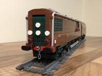
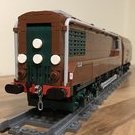
Oh yes!! I remember seeing your thread last year when you re-introduced this MOC and I'm glad to see how it's progressed. I really like the way you've kept the retro look of the loco but still made it instantly recognisable. Just to clarify and expand on the lighting points. The central headlight was not carried by any of the Deltics until after they were withdrawn and entered preservation as they were not required for mainline running at that time. However, for any preserved loco to have been used on the mainline these would have been needed and so they were fitted. The backlighting for the headcode blinds and later "domino" arrangement was very faint and even when the headcode boxes were plated over and lights fitted these were never considered to be "headlights". In railway parlance they would be referred to as "marker lights", very much light the sidelights on a car, and driving a train at night without a headlight could be an interesting experience. The loco's tail lights would be similarly dim and would only be used when the loco was being moved without a train, otherwise they would be left switched off. Oops!! -
OcTRAINber 2019: The Technic Challenge is gearing up!
Hod Carrier replied to raised's topic in LEGO Train Tech
I’m confident that I’ll be finished by the end of October, but not this October. I’m afraid that I’ve been hampered by developmental setbacks and delays in receiving orders to such an extent that I’m still mired in the testing phase with no clear idea yet when I might start building. I’m so far behind that I’d need an extension until Christmas to have any realistic chance of entering, and that really isn’t fair on everyone else. As a consequence I must inform you that I’m out. -
[ MOD ] Apollo 11 Lunar Lander 10266
Hod Carrier replied to LemFliggity's topic in Special LEGO Themes
Awesome build!! Congratulations for getting it all complete and for making it so accessible for other builders to replicate. I like the way that you’ve added a little more play value (or perhaps I should say pose-ability) to your build with the opening hatches and folding landing gear. Top work, sir. -
[ MOD ] Apollo 11 Lunar Lander 10266
Hod Carrier replied to LemFliggity's topic in Special LEGO Themes
They came from Minifigs.me -
[ MOD ] Apollo 11 Lunar Lander 10266
Hod Carrier replied to LemFliggity's topic in Special LEGO Themes
Whoops!! That’s how they came out of the box so I didn’t spot the error. Many thanks. -
[ MOD ] Apollo 11 Lunar Lander 10266
Hod Carrier replied to LemFliggity's topic in Special LEGO Themes
@LemFliggity Thanks for the amazing response. I'm really pleased to have been able to deliver such a good finished article and to have drawn such high praise from you. As a man who clearly knows his onions when it comes to the Apollo spacecraft it's gratifying to get your feedback. I'll admit that I could find a lot more source material for the ascent module, including photos of the interior of the ground training simulator, to supplement the various schematics and diagrams. Therefore I had a better chance of getting the details right than I had with the descent module. Of course I could not overlook the aft compartment. How could I possibly resist the temptation to steal such a great idea . It was a bit of a puzzle to include the oxygen and helium tanks as well as the electronics rack, but by making the rack as flat as possible (only 2 plates) and trading off against the amount of detail depicted I was able to create sufficient space. Yes, those are 3L bars at the top but they are not structural. Even though these details, along with so many others, will stay hidden in normal display it's nice to know that they are all there. Having now completed my build I think that there are some details I may change in the future, including those S band dishes. But for the time being I am happy to leave the build for a while, step back and just enjoy it. But I'm still keen to see how you've depicted this famous craft and will be watching developments with interest. However, and not wishing to hijack your thread, here is a little snap of the finished article to spur you on. -
[ MOD ] Apollo 11 Lunar Lander 10266
Hod Carrier replied to LemFliggity's topic in Special LEGO Themes
Building in LEGO is always a horrible compromise between what looks best and what is possible, hence why I've taken a few different turns with regard to things like tank shapes and size of the landing radar array. It's always nice to see different approaches taken by different modeller, and I'm glad that my improvements meet with your approval. Speaking of which, have a look at my ascent module and let me know what you think. I'd be very interested to get your feedback. -
[ MOD ] Apollo 11 Lunar Lander 10266
Hod Carrier replied to LemFliggity's topic in Special LEGO Themes
Well I can't speak for anyone else, but I'm hooked. Don't be disheartened by the lack of replies. Your thread is getting good numbers in a forum that is inevitably a bit of a "catch-all" for all the themes that don't have their own dedicated areas. I've been getting on with my own build and have both stages almost complete. I haven't been as organised as you in terms of getting things photographed and described, but I have managed to take a few quick snaps to show some of the alterations I have made. One of the main changes was to have larger propellant and oxidiser tanks for the descent engine. I've needed to change the back of the quads slightly to accommodate them, but they are nice and snug. Without good source material for the underside I have taken a bit of a guess and covered up a lot of the exposed details using additional plates which also act to give a little more depth to the area surrounding the engine. Like you I have also remembered to include the landing radar and it's heat shield. There's more to come on the ascent stage. Although I've not yet taken any photos of that I'm excited to share it and to get your feedback. -
OcTRAINber 2019: The Technic Challenge is gearing up!
Hod Carrier replied to raised's topic in LEGO Train Tech
Oh yes!! It's that time of year already. I like the category this year. It's very innovative and will surely have us all needing to think outside the box. I'm really looking forward to seeing what everyone comes up with.