

futtigue
-
Content Count
14 -
Joined
-
Last visited
About futtigue

-
[WIP] Lifted Subaru Ute
futtigue replied to VKTechnic's topic in LEGO Technic, Mindstorms, Model Team and Scale Modeling
Looks very very good! Love the suspension design! -
Pneumatic Engine using new large v2 cylinders
futtigue replied to futtigue's topic in LEGO Technic, Mindstorms, Model Team and Scale Modeling
That"s awesome. What layout did it use? Vee or Inline? Pushrods or Camshafts? Do you have any pictures you could post? I'd like to see how others tackled this problem. -
Pneumatic Engine using new large v2 cylinders
futtigue replied to futtigue's topic in LEGO Technic, Mindstorms, Model Team and Scale Modeling
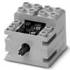
It is not much different from modifying regular v1 pneumatics. I was very worried because of the high cost of the large cylinder (especially when I ordered them a while back, as they were even less common) if i messed it up, but also the smaller diameter of the hose inlets. It seems TLG has gone with that new 'stepped' inlet so as to make it easier to squeeze the hose onto it. I was nervous that this new reduced diameter would not hold up well to drilling the hole out larger. Because of this it is very important to make sure you are drilling in straight. I see some of the pneumatic 'grand masters' out there recommend a drill bit of 1.8mm. Even though we use the metric system here, twist drills are all still fractional. So I took a conservative approach, and stepped down (rather than up) to a 1/16th" bit, which is equivalent to a 1.55mm. This still dramatically increases airflow into the cylinder, but is a bit safer when considering the thinner wall of the end of the inlet. Avoid using a hand drill, as once the drill checks through the inlet it will drop down into the cylinder and you will begin drilling out the other side. If you must use a handheld drill, get a drill stop, or do what I did and use a crappy drill press set not to exceed half the depth of the piston. One of my holes (the second one I show the camera in the video) did not drill straight in, and you can see the lower inlet on the last piston was ovalled out. This does not seem to affect the operation, and all pistons seem to seal very well still. When you hold the inlet up to the light, you can see the very thin area on the wide end of the oval (its thin enough as to appear translucent). I figure, even if this end does break off, there still should be enough of the thicker portion of the inlet left to hold a hose on. I just kick myself for only ordering 4 cylinders instead of 5, as I would have been very mad if I had to do another order just to replace one I wrecked! Next I'll be modifying more valves, and hooking it up to a real compressor. There are also areas where the engine can be improved yet. Anyways, I hope that helps in the construction of your own engine. Let me know if you are curious about anything else. -
Pneumatic Engine using new large v2 cylinders
futtigue posted a topic in LEGO Technic, Mindstorms, Model Team and Scale Modeling
Hello everyone After fiddling with my LPEs for some time, I have finally managed what I think is a first: a running engine using the large cylinders from the new V2 pneumatics series. Like many of us, I was very worried once linear actuators appeared that LEGO had given up on the expensive pneumatics. So I was very happy when they released the V2 system with the Mercedes Arocs set. Well some time has gone by and I simply have not had the disposable income to grab the set, so I finally stopped making excuses and just ordered some of the new cylinders off of ebay. After seeing how high the friction was on the cylinder, I immediately set about modifying them. I drilled the opening slightly larger and added a small amount of finer silicon lube. I ended up with a very large inline-4 with twin camshafts. It runs at a very low rpm but with a lot of torque, easily the most powerful LPE among the ones I have built. Here is the video of me modifying the pistons and running the engine. I owe quite a bit to builders like DrDudeNL, LPEPower, NCJanso, and many others! I started out following their instructions and copying their ideas, until with enough time and practice I came up with tricks and a style of my own. I am quite proud to show the first large cylinder LPE (...I think. Let me know if there has been another one forst and I will give credit). Anyways, let me know of you have any ideas or suggestions for improvement! -
[TC10] Ikarus 280 Non-Articulated Bus
futtigue replied to josszo's topic in LEGO Technic, Mindstorms, Model Team and Scale Modeling
This is a fantastic build! Pneumatics are a perfect fit for bus builds, with the doors and kneeling functions and so on. I'll continue following this topic, good luck with the build! -
Hydrostatic drive
futtigue replied to Kman860's topic in LEGO Technic, Mindstorms, Model Team and Scale Modeling
I would also be interested to see if someone can pull this off. I have tinkered with Pneumatic automatic transmission designs that use a "fluid" coupling rather than a direct mechanical connection. This usually ends up in me building a terrible approximation of a pneumatic engine connected to a pneumatic pump, which is a pretty poor way of transmitting power. Despite all my failures though, I remain fascinated with the concept. -
External Compressor
futtigue replied to andrewganschow's topic in LEGO Technic, Mindstorms, Model Team and Scale Modeling
That link was to an Australian or European site. They dont need to be 220/240v, in fact every single one ive seen here in Canada is 110v. If you're in Canada or the USA it should actually be very hard to find a 220/240v one. -
External Compressor
futtigue replied to andrewganschow's topic in LEGO Technic, Mindstorms, Model Team and Scale Modeling
Exactly - and we are comparing two different states. There is no need to compare the temperature drop of liquid air as it expands vs. liquid CO2 as it expands, because we are not using liquid air. It only makes sense to compare the two sources we can use - HPA (a gas) as used for paintball, and CO2 (a liquid which boils off a gas) as used for paintball. I understand that both might see a very similar (and harmful to Lego) temperature drop were they to start out at the same pressure. But, for our practical purposes, they do not. Which means High Pressure Air from a light, portable paintball (or possibly even SCUBA) tank would be far superior to a CO2 paintball tank (which would be cheaper). This is something that could be used to power vehicles with pneumatic engines, without having to follow it around with a hose! -
External Compressor
futtigue replied to andrewganschow's topic in LEGO Technic, Mindstorms, Model Team and Scale Modeling
Sure, but doesn't expanding Co2 create a much lower temperature as it turns from liquid to gas than high pressure air would? I mean, when a paintball gun with a c02 tank is fired enough, you can see 'snow' emerging with the markers. I dont believe this occurs with HPA, but admittedly I am not a paintball expert. -
External Compressor
futtigue replied to andrewganschow's topic in LEGO Technic, Mindstorms, Model Team and Scale Modeling
JGW3000,that is an excellent idea with the fish tank compressor. That never crossed my mind. To revisit my first post, here is someone who used a combination of 2 modified regulators to step down 2500 psi HPA from a paintball tank to 100 psi for an air nailer. If this is possible, reducing pressure to the 40-90psi range that Lego Pneumatics top out at shouldnt be much more difficult. -
External Compressor
futtigue replied to andrewganschow's topic in LEGO Technic, Mindstorms, Model Team and Scale Modeling
Ive often thought about this same thing. I have a large compressor in my garage, and can run pneumatics through a regulator and nozzle that you would use to inflate a football. Of course, this is inconvenient, as the garage is detached, unheated, and the compressor is very noisy. Two solutions Ive been considering as I slowly bring together the parts for my own Pneumatic Engine are: Using a small, quiet desktop compressor sold for hobbyists airbrushes. These are much quieter than typical garage compressors, as they are meant for indoor use. They will not provide the full 90 psi that a shop compressor would, but 40 psi should be fine for lego. The other solution (and this is the one I am looking into, as my Lego Pneumatic Engine might eventually go in a vehicle) is to use an HPA (high pressure air) canister from a paintball gun. You cannot use a C02 canister, as C02 cools as it expands, and I imagine this would be very damaging to the soft rubber seals in Lego pneumatics (not to mention the moisture). HPA tanks are a bit more expensive (50 or 60$ Canadian or so) and hold air at a very high 2000-3000psi (requiring another regulator) but are light and portable. Right now I am trying to find a fitting that will connect the special paintball regulator thread (that will not adjust down to below 500psi very accurately) to a regular compressor fitting for a 0-90psi regulator to bring the pressure down safely. From there I would it a handle, and ball inflator nipple. Hopefully this provides you with some ideas, and maybe someone else has tried one of these. -
Im back with a new MOC! This time I decided to build something Canadian, and even if they did build only four of them I decided on the Canadair CL-84. The real 84s were built in the seventies, and unlike the modern-day Osprey which is simply a tilt-rotor, the 84 is in a tilt-wing configuration. It was very stable, and even saw trial with minigun pods, sling loads, and with carrier operations, but at the time no one seemed willing to bear the large cost of then-young tilt-wing technology. Additionally, its biggest potential customer, the US Navy had an issue with the 'not built here' side of things, and it never went into full-scale production. The version I built is a variant that was planned, but never existed. Though real 84s carried drp tanks and even tested with miniguns, I have been unable to find any pictures of this configuration. Finally, out of mere convenience and cost, I went with white and black rather than the gray, red and back that they usually appeared in. The wings are fully tiltable to 100 degrees, just like the real thing. The tailplane also folds down, and all rotors spin. The landing gear is mostly retractable. I didnt have room to make a nose gear door and still have the landing gear strong or the ability to seat pilots, so I just left the exposed wheel. The sponsns for the rear wheels did seem to work out well though. So theres mostly an interior. The jump seats wont fit minifigs, and are just there for looks. And speaking of minifigs, these are the pilots! Let me know what you think of the plane!
-
Thanks everyone for the responses. I 'll soon be making some changes based on your suggestions to get this thing as close to real as possible, or at least until the bricklink order for my next project comes in. I thought the same thing. I tried taking off the roof top slopes mounted on the front to shorten it a bit, but then it looked too boxy. I want it to be shorter but stay curved, so standard slopes are not an option. I may try mounting some 2x4 modified Bricks with curved tops sideways as they will be shorter, but I'll have to play around with the chin bubbles to make that fit. It's alright, this is exactly what I was looking for. Good one, I didn't notice that. There really are only two different pictures and a video of the few prototypes, (and even those two are pretty different) so I must have gotten confused with the photos of the standard production versions I was looking at. I'm thinking of using the slightly larger technic wheels for the front, and then the double airplane wheels at the back to still give it that upward slant. I tried it with two studs wide, and I was unable to get it to slope down enough for it to look good. With only the two thicknesses of plate to work with, they end up looking kind of flat. It's not entirely accurate though. Thanks. I dint think of moving the engine forward, but I did think of making it a little shorter. I considered using a standard 1x1 cone for the exhaust rather than the light bley palm tree part (which to me seems the perfect thickness but a little too long). I may try lengthening the entire pylon by 1 stud, maybe two, and moving the engines up a bit. As for the front rotor axle, there is no other place to mount it. The wedge pieces I used to make up the front of the pylon do not have any room to move the axle farther forward, and I haven't thought of a way to achieve that shape with different, more hollow pieces. As for the sponsons, I am realizing that now, and may use the corner slope brick (but upside down) on the part where the aft of the fuselage joins the tank. Ill play around with it tomorrow or the day after and see what looks good. Thanks for all the tips. Pictures will be up as soon as I work out some of these kinks.
-
Hello all, This is my first time posting here, and I've uploaded pictures of my first MOC since I stopped building about 6 years ago. I decided to build the prototype version of the CH-47 Chinook, which was called the HC-1b for evaluation tests by the US Army. I chose to build this specific Chinook as I loved the colour scheme and the fact that it was a little more unique than others. Rather than the four round windows and single side door of the production Chinook, it had five windows and only an emergency escape hatch close to the cockpit. I plan on doing a production version with the standard gray colouring, and with that one I'll fix some of the problems this model has. I think I got the proportions a little wrong, as the fuselage seems a little too long and short. Additionally, the rotors are not geared together, and there is absolutely no interior access whatsoever. These will all be fixed on the next version I do though. Among some of the things I'm proud of is the cockpit. I really like the shape of the chin bubbles, although you really have to cram a few minifigs in there. I have to give credit to Mad Physicist's Chinook, which I stole the idea for the windows from. His is really the best looking Chinook I've seen built, and his Sea Knight was kind of an inspiration as well. All in all, it took about five Bricklink orders at around 100$ total to get this done. I have LDraw rough draft files if anyone wants them, although a LOT changed when I actually started building. I've estimated it at around 620 to 670 pieces. Nearly all the Dark Bley I had to order, since I've not touched my LEGO since I was fourteen and have none of the new colours. Anyways, I welcome any feedback or tips to make it better, and I'm waiting on some more orders so I can hopefully finish the B-25 Mitchell I have planned out for the next few weeks. You can find the whole Flickr set with some construction photos here. Thanks for looking