

zephyr1934
-
Posts
4,464 -
Joined
-
Last visited
Content Type
Profiles
Forums
Gallery
Everything posted by zephyr1934
-
For the moment I do not have an eloquent way of attaching rods to the small train wheels that come with the PF motor. Short of drilling a hole for a technic pin in the wheels (I'd do it from the backside, using 60483 connected to the existing axle hole as a guide), the best I've got is using a 2 long thin technic beam, e.g., LEtsGO's drivers above or a technic crank e.g., my little Porter (I borrowed this idea from someone else). I MIGHT be able to figure out some way to clip on to BBB small wheels, but that would be a lot of work to get a satisfactory connection so it is way down the road. I doubt there would be much demand though, since you lose the traction of the bands on the lego small wheels. Modified BBB medium wheels solves the connection point problem, but still does not address the traction problem (some folks have machined a grove into the BBB wheels but it is non trivial). As for the rods, I already have the solution for BBB medium drivers. I made a 4 hole 10 long connecting rod (do not adjust your set, yes, this is in white, it is for a customer who wanted to paint it). This design is not yet in my store since I have no idea how to keep from confusing customers with the subtle differences between my normal rods and this thin design (and whenever it does hit my store it will be in gray). and it can also be fabricated without the thin grove, yielding the middle rod in the picture below, Note that this wheel spacing only works if you modify the BBB medium wheels as was done in bricklink user ulimy's example noted above (ulimy does some great work). These rods can be fabricated with larger spacing between the holes for non-modified wheels as well as the larger wheel designs (e.g., here). Returning to the small wheels for a second, while talking about three axle trucks/motors, recall when the RC motor first came out the bands would slip. Then Cale/SaveTheAggie solved this problem using thicker o-rings purchased from a hardware store. Although it would appear that lego has solved the slipping band problem that the original wheels had, with three axle trucks the thicker o-rings still offer an advantage when placed on the outer axles. I used this technique for the powered 3-axle trucks on my SP Pacific tender (with wider wheelbase than you would have in a PF motor) and it lifts the center axle (without the thicker o-ring) sufficiently off the track that I have not had problems in curves or switches. Oh, I totally hear you. I would agree that the prices are high, but that is where they need to be. I am able to distribute the fixed fab costs over many rods by fabricating a lot of rods at one time, but even totally eliminating the fixed costs, the unit cost of fabrication per rod is still high. Not to mention the time put into design and finishing. I am not getting rich. So these rods are for the individual who is looking for that detail on their locomotive. This is the finished product, so yes, the surface is matte and a little grainy when viewed close up. I wanted to show the detail shots so there would be no surprises. Given the price, I want to do all that I can to ensure the customer is getting what they expect. I personally think it looks tons better than pinning together a bunch of shorter technic half beams (which is why I made these for myself in the first place) and they are particularly handy for the long spans past 7 studs where you previously had few alternatives this thin. No problem if these rods are not for you. If you are on the fence, I'd suggest starting with a single locomotive, e.g., as Duq did, and see how you like them. Then, if you find you do like them and have big ideas, certainly we can talk off-line. Thank you Locomotive Annie. I would agree with both you and Commander Red Hat on this one.
-
Does Aerodynamics Affect Train Speed?
zephyr1934 replied to Electricsteam's topic in LEGO Train Tech
6 or 8 drivers could be 8 blind drivers that never touch the rails, then use a pair of PF train motors as the pilot and trailing trucks, e.g., from brickworld 2010 I think it was someone from NILTC had used flanged drivers and raised them off the track This photo is unflattering, but when it was running you wouldn't notice (it took me a day or two to catch it) since the drivers had a separate motor to keep the rods spinning. Also, it sounds like your race is from point A to point B, but is it from a dead stop or can you pass point A at speed? If the latter, you can add gearing after a PF medium or XL motor to speed it up considerably at the expense of torque and probably acceleration. So is your competitor also reading the forums? Or will this turn out to be a race between the EB advice and the Flickr advice? (grin) -
Looks like the baseplate is the hardest part to fake. Have fun...
-
Garden Railways - A Lego Layout in the Garden? Is She Nuts?
zephyr1934 replied to Locomotive Annie's topic in LEGO Train Tech
Why don't you find the spot in your yard that gets the harshest sunlight and put one or two pieces of sacrificial track out there right away to see how well it weathers? Assuming you are a few months off from actually building anything outside, this experiment will give you a minimum number of months to expect your track will survive. -
Thank you all for the kind words. With these new valve gear bars I'm working on something like 20 new parts (I'm going to see if I can push both the 3mm and 2mm thick bars all the way out to 8 long). I can TOTALLY see why rods and bars just are not feasible in terms of small scale production without the rapid prototyping. I just tried the 2mm rods on v3 and they look real sharp and it works fine, but the technic pin is a limiting factor (you don't want a pin sticking back from the valve gear knocking against the side rod). So the 3mm rods will be better in some applications (e.g., the rocker bar in v4). I want to rebuild the frame for v3, hopefully add a motor and then I'll post photos with the 2mm rods. I hope to make the bars available in Dec so that folks can start playing with them. More on these developments soon. Heh heh. At first I was wondering what the heck you were talking about, but yes, from the side view the running board really does look like a piano keyboard, doesn't it. As soon as you get some elevation you see through them and it looks more like the grillwork I had intended. I wanted to get the band of silver there and keep the running boards "light". Her sister, my A3 (the middle locomotive in this shot) is worse, but the checkered flags gave me the thin white stripe necessary for the profile shot. Ah compromises. Wow, that is a very nice locomotive. Given the fact that you used mostly basic brick and plates it is fantastic (none of this cheese slope cheating the laws of physics stuff). I'm guessing you built it around 2000 or earlier. It looks comparable to the cutting edge designs prior to BBB wheels (excluding the occasional steamer that had machined driver wheels). I think Dan Siskind had similar driver wheels on one of his designs of that era. My first engine from about that time was an 8 wide diesel switcher with rubber tires and similar basic brick design- although it might be a little clunky, it has nice detailing given the resolution and I still proudly display it on a shelf in my office.
-
Conversion of Power Functions to 9V Track
zephyr1934 replied to The Lego Wizard's topic in LEGO Train Tech
Cough... As a mostly 6 wide builder, I have to agree with much of the assessment. Though I am close to neutral between the two, both have their places where they excel (if I were starting from scratch, I'd just save the money and go PF). The two things that PF delivers that 9v doesn't is: much higher pulling power (even with the PF train motor, but especially with the XL motors), and the ability to sustain much lower stable speeds. -
That's a great looking engine. I bet putting the decals across the doors will be nightmare though. Looking at the cab, it is too bad the new 60592 windows do not yet come in gray Though black MIGHT look okay. Or you could use the old 7026 windows. The price on yellow isn't too bad, but gray is out of the ballpark. (after clicking on the image, scroll to the bottom left for a few variants that are listed separately) Your engine is a fantastic build no matter how you slice it, but doubly so for a first MOC. A word of caution though, you have chosen a prototype that is VERY difficult to get running well in 9v. Hopefully I'm wrong about this, but if I am right, don't let that discourage you from building more MOCs. Why am I all doom and gloom? The long wheelbase will create a lot of drag on the curves. And an engine like this should be pulling at least 20 cars (grin), which is also a fairly heavy train by lego standards. On the power side, you probably shouldn't use more than two 9v motors (the recommended limit) unless you are prepared to occasionally burn something out (either a motor or transformer). I will occasionally run three 9v motors on one transformer with a not-too-heavy train and occasionally the transformer's overload resistor will trip. I have also run up to six 9v motors using three transformers on one track, but I suspect that isn't great for the transformers (attempt at your own risk). Assuming you stay within the manufacturer's limits, I find that the stock Super Chief (two locos, five heavy cars) runs okay with two 9v motors and I use that as my rule of thumb for the upper limit on 9v motors. The 9v motors have limited pulling power and the long wheelbase of the locomotive will make it all the harder to overcome. If you do contemplate other designs, rather than rebuilding your entire locomotive, you might want to build up some simple mocups and see how well they run (base plates, some weight to improve traction [either bricks or a coffee mug], but no aesthetic designs) so that you can rapidly test and revise your design. I suspect a pair of PF XL motors would be the way to go, but there is no place to hide them on this locomotive. However, making the locomotive unpowered and stuffing the two XL motors in the first boxcar behind the locomotive is definitely doable. That photo shows the inside of the tender of my SP Pacific. I've pulled over 50 cars at one time with it without problems. The XL motors should give you the kick you need to push this engine and pull most of your remaining cars. It won't be speedy, but as SavaTheAggie once said, that design can push a Buick. In any event, an excellent build. Benn
-
I'm not familiar with the Virginian electrics, but I know Milwaukee Road had AB pairs like that. I'm surprised no one commented about the catenary and the folks on top (zap). Presumably the shot was taken away from the wires. I have a crazy locomotive MOC, the ACE 3000. More details on my build can be found in REC in RailBricks 6. One of these days I'll upload more photos to brickshelf. and more info on the prototype here.
-
If that is an eight wide cab, you could keep the curve but lower it by one plate using 88930:
-
It took a little longer than anticipated, but I've tried the 3mm thick valve gear out and I am quite happy with the results. I've uploaded detail shots of all the new bars here, and they will be visible once moderated. First, I simply updated the v2 concept to use the new bars (click on the image to see the individual frames once the folder is moderated) If you look closely, you'll see that I've also updated the cylinder in preparation for v4. Ultimately I plan on putting these under a new 4-8-4, but for now I borrowed by Milwaukee Road S3 to try the rods out, here is a shot of the previous drivers next to the new drivers This locomotive design uses 9v motors for the pilot and trailing trucks and the drivers are simply dragged along behind the front motor. As such, the cylinders have to be fairly wide to clear the motor on curves and you do not have much space to actually build the cylinders (I did not think to get a detail shot of the cylinders, but I will try to do so soon). In the end it came out to be just under 11 wide. I tried to take an unflattering photo of the build, but aside from blurry shots, I couldn't find an angle where I thought the valve gear protruded too much (see examples in the folder once moderated) I would caution that it is hard enough to make a steam locomotive run well with just side rods and connecting rods. So I would recommend that you do not wander too deeply into the valve gear until you are comfortable building and adjusting technic constructions. The running gear in v4 might look simple enough, but it was actually a fairly complex build. As noted in an earlier post, I cut down a pair of 3x3 technic half beams to 2x2 to anchor the eccentric behind a blind driver (you could probably keep it unmodified behind a flanged driver). I also cut down a technic axle pin with towball to connect to the eccentric (inspired by LT12V). Using the 3mm thick valve gear bars, the bar connecting to the eccentric and the rocker bar have the cuff turned to the inside of the locomotive- to keep the pin heads from knocking against the side rod. Then the final bar had the cuff turned away from the locomotive to facilitate connecting to a black 2 long technic beam behind it. The end point of the valve gear and the side rod differed too much to use the 2 long valve gear bar to connect the valve gear to the piston as I did in v2. The valve gear look great at slow speeds (click here for a short movie) and I've run the locomotive for a few hours without any trouble. Since PF does much better than 9v at slow speeds, I suspect PF is where the valve gear will really shine. I use a third party for the fabrication, but then I inspect all of the rods and do finishing work to ensure they will run well. My biggest problem is variability in the hole diameters. I've often contemplated attempting other connectors (e.g., a technic axle or axle hole) but given the variability in the holes, I don't think that would be feasible at this time. It is amazing what the difference of 0.1 mm will do.
-
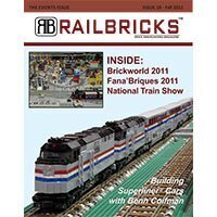
Look what I got... just finished today. I hope to try these on for size tonight. The picture shows four different types of rods or bars. The two biggest rods are my normal side rods and are included for reference. The far right show the batch of 3 mm thick valve gear bars, these have cuffs to clear the clips on technic pins. The top left show the 2 mm thick valve gear bars, they have a smaller ring around the pinholes and no cuff (hence they are 1 mm thinner). These two groups of bars are both 2 mm tall (measured in parallel to the plane of the photo). Then the bottom left shows 3 mm thick and 3 mm tall prototypes that probably will not be used for bars, but might evolve into a lighter variant of the driver rods. Note that the three-hole rocker bars were just to get the holes in the right place. The final versions will probably have a little more elegance to them.
-
New Option for Dual Motor PF Locomotives
zephyr1934 replied to mostlytechnic's topic in LEGO Train Tech
I did the same thing on my F40 (Railbricks #10, p42 for a detail shot). Works great (though I too had to use an extension wire). You can fit a plate or a tile under the PF wire leaving the motor, something you can't do with the stud based power connector on the RC and 9v motors. -
Very neat stuff, particularly for the prospect of pulling long and heavy trains. Though the fact that they can uncouple on bumpy track is a bit of an impediment. Thanks for posting the details and please do keep us posted if you have further developments.
-
I have powered PF lights from a 9v motor. The only problem I've had is that the LEDs flicker off at low speeds (and thus, low voltage). I haven't tried powering a PF motor from a 9v, but I believe many folks have. It will certainly require the conversion cable to take power off of the 9v motor, but on the PF end of it you could then attach both the lights and the PF motor. You may have to turn the PF motor backwards or use a polarity switch though.
-
That is a very nice build and I like how your attention to detail went beyond the train to include the catenary and brick built track. The articulation is fantastic and making anything run on 4 wide track is excellent.
-
I would have gotten away with it if it weren't for you meddling kids! Kudos to BMW, who has sealed the 4th and final spot, he has illustrated the technique I used on v3. Cale, however, has secured the secret 5th place spot (would have been 4th, but he was slow to post) by coming up with my other solution, shown below. So free s/h on an order of rods to both of them as I call this competition to a close. And a special nod to Duq for doubling down. Before getting to BMW's solution, I tried Cale's solution first on a blind driver but the 3x3 lift arm kept knocking against the adjacent flanged drivers. It should work on the back side of a flanged driver though. Cale's design has one distinct advantage over the other two solutions, you can put a 1/2 bushing on the drive wheel's axle to hold the eccentric assembly in place. My current thoughts are to do just this for my own use and trim the ends of the 3x3 down to 2x2 for use behind a blind driver.
-
Simply fantastic, the piping is just icing on the cake (incredibly detailed icing that is)
-
Very good designs Cale, but in my earlier post, http://www.eurobrick...2 I had intended to clarify that the friction pins were out of bounds. My reasoning is three fold, 1) LT12V just did it, 2) I need at least 1.5 studs beyond the wheel to accommodate two rods and the eccentric, and 3) I don't trust the friction too keep it in place long term. Your first design is the best non-gear submission thus far, it is good enough to win if no one comes closer, but there is room to come closer. My solution will keep the eccentric from rotating on its own axis and it does not use any glue. So the competition remains open but we will have the 4th and final winner by the end of the contest.
-
Nice work
-
One of the biggest challenges with lego steam engines is figuring out how to make them work well on uneven track. Unlike most diesels, often steam engines have three or more sets of wheels on the track. If they are in a rigid plane, you'll likely have one set of wheels lift off the track when you hit a bump. If your layout is nice and flat (e.g., on the floor) it shouldn't be a problem. If you are contemplating bumpier terrain, then I'd suggest starting with the mechanicals and making sure it behaves when going over a bump (my test bench is an unconnected plate or technic axle placed under a rail joint, see "Northern Exposure" in Rail Bricks #5 for a few photos of what I mean). I've gotten to the point where I can handle some serious bumps (grin).
-
I've had two more successful submissions, the first came from Duq, pointing to LT12V's solution that was posted on bricklink, below. Since having an encyclopedic knowledge of other people's tricks can be just as handy as inventing it yourself, I would call that a win. The next came from Daedalus304 and looks like he independently reinvented the same technique. Both Duq and Daedalus304 are have qualified for the free shipping on an order of rods or $5 off s/h of a bulkier order from my store. Daedalus304 solution is not yet public, but because it only shows the critical components it might be easier to absorb. I'll try to remember to link to it when it does go public. So far all of the solutions have used the same paired 8 tooth gear trick. I will call that approach closed for this competition. However, I did not use any gears in my solution. So I will leave the competition open to one more winner if they come up with a different working technique (previous winners are excluded from winning this competition a second time). -----------Edit------------- One potential hazard I see with the paired gears is that if there is a technic hole right next to the driver's axle hole, the gear could slide into it and get stuck. Here's Daedalus304 solution, same idea as above, but with most of the locomotive cut away. ----------------------------- Now that is an interesting idea. I don't think I could fabricate pins, but I'll scratch my head and see if I can come up with something else that would fit and would be sufficiently durable (but it will be a little while, since there are several other efforts already in the queue). The technic engine cam shaft only reaches 1.5 studs, though as you can see in the detail photo, the outside consists of a 2 long half thickness technic lift arm on a technic axle (mimicking the form of the technic cam shaft). The hard part is figuring out how to rotate it 45 degrees while also securing it. And sure, no problem, my comments about your crocodile rods would apply to anyone. I want to get the holes in the right spot if I can. The reason why no one has produced rods in the past is the vast number of different designs you'd need. So in that sense, the rapid prototyping is ideal. Unfortunately though, there are few economies of scale to be had, which is why the costs are as high as they are.
-
And to help camouflage your stickers printed on white paper you can go around the edge with a felt tip pen to hide the white edges.
-
Well that took about an hour to get a working solution (and one probably better than mine). LT12V gets the first place honors, Congratulations! But that shouldn't be surprising since I cribbed off of his brilliant work in the first place. Fortunately the reveal was over the messages, so I'll leave the challenge open for 2nd (and further?) and will offer the same prize for 2nd (possibly further). Correct, no glue (for heaven's sake, "glue" is a four letter word don't you know? Then again, so is "lego"), and to clarify the design, there is at least a full stud clearance between the wheel and the eccentric to accommodate both the side rod and connecting rod. So the friction pin solution in LT12V's picture above would not work for this design.
-
Nice work. Though be careful, you'll soon be building expansive trains (grin).
-
As promised, here is version 2 of the running gear Click on the link to see the individual frames. At this point it is all Lego except for the drive rods. Note how I've used technic half beams to work out the geometries. Everything beyond the pivot points will ultimately go away. I will be replacing the technic beams with custom valve gear bars. For now I am keeping the pin connector, but will be attempting to make 2 mm thick bars. I'm trying two different versions of the bar: 2 mm tall on the left and 3 mm tall on the right, in comparison to a 9 stud long connecting rod in the center. This first fab is to see if the bars are durable enough and If they are, there is still a little more work to do, e.g., dressing up the rocker bars. Meanwhile, I pressed on to version 3 of the running gear (can you see the LT12V's influence?), Again, roughed out in Lego to later be replaced with custom bars and click on the link to see the individual frames. Look closely, you will notice I used an eccentric This assembly is pure, unmodified lego (though like LT12V, I will ultimately trim the pin portion off of the axle pin in the photo). So now the challenge goes out to anyone interested- reverse engineer this eccentric. The competition is for the glory. If you think you've got it working you can post here or contact me via Eurobricks messages. The first correct answer will get free shipping and handling on an order of custom rods in my bricklink store or up to $5 off s/h if you order other items too (assuming that is allowed within the Eurobricks TOS). The contest ends when we have a winner or I'm ready to make the bars publicly available.