
Lok24
-
Posts
1,241 -
Joined
-
Last visited
Content Type
Profiles
Forums
Gallery
Everything posted by Lok24
-
Hi Rob, oooops!! I forgot to post the link (now I edited the original post), but of course, here's the video (1 min.)! It does work without it, but if you dont stop, the motor will - at the end of the rack - turn the complete bogie! That's what the stop (1x2 liftarm upper right) is for. And without the clutch the motor still gives much power to the complete construction and might damage it. cu Lok 24
-
Hi all, recently I presented remote decoupling in a separate wagon, today I want show a locomotive with the complete mechanism. Link to a short video (1min) The engine itself is very simple, basesd on the set-60098 Heavy Haul Train. I wanted the complete technical stuff to fit into a locomotive with the Lego-standard dimensions, that is 6wide, 32 studs long and 10 bricks high, span of the bogie centers is 18 studs. on the left: PF train motor, receiver and battery box in the middle upright: the motor for the decoupler on the right: gear for the decoupling mechanism The standard bottom plate (2 plates high) could not beused since the right bogie builds quite high. Therefore, stringers were used over the entire locomotive length. The force is transmitted via a bevel gear on a pinion which moves the rack in the bogie with the magnetic coupling. The problem: the way of the rack must be limited, otherwise the motor rotates the whole bogie. Given below is no space, the stop is installed above. yellow: drive from the motor to the clutch (which could be much easier with more space) green to bottom: the output of the slipping clutch down on the bevel gear and thus to the toothed rack with the coupling green to right: moving a vertical axis upwards with a 1x2 Liftarm as a stop (blue arrow) The bogie alone, the support removed. On this support the entire chassis is hold up, the connection is made only by the drive axle (in the picture above the four red arrows). The construction is based on an idea by Thomas Selander, presented in Railbricks. 13 Perhaps this is suggestion to try it, it really works fine, as I showed on the last exhibition in august. cu Lok 24
-
Thank you all for your interest and the positive feedback. Hi Mestari, No, not at all I have a home office with less the 10m², containing shelfs, folders,desktop and pc and so on. And there is one(!) wall 4 meters long with all my LEGO in shelfs and boxes, and a plate to build on. That's all. The BayWa I build in about 5 weeks for the exhibition only and could store it on a small table aside. Meanwhile the building is dismounted (app. 5500 parts) and sorted again, I don't have any big models or even a railroad layout here. cu Lok 24
-

[EV3] Tiny Fork Lifter
Lok24 replied to Lok24's topic in LEGO Technic, Mindstorms, Model Team and Scale Modeling
Hi, Here is the solution: the ramp is separated into two parts, the one in the background is fastened normally, as you can see here The other half, in the front, is placed on pillars, which can be moved So there is a very small gap for the card, for the curtain it can even be smaller and is nearly invisible. cu Lok 24 -
[EV3] Tiny Fork Lifter
Lok24 replied to Lok24's topic in LEGO Technic, Mindstorms, Model Team and Scale Modeling
Hi all, thanks for yout comments. Please let me explain some details: Much more than 500 in 2x7 hours - but with few errors, in most cases the barrel didn't roll properly, due to the slope is very smooth. But perhaps 5% error - not that bad. I was surprised how precise the EV3 and the sensors stop. This is why I used the card like shown in the first picture for the exhibition. But the "Cloth Curtain" from the T1 Camper works fine as well, it's kind of a thin foil. There were some kids, perhaps 10 or 12 years old, who explained it to me... They got a litte reward: I then removed the complete building to show them the assumed mechanism. cu Lok24 -
Hi all, thanks for your comments. not big enough here are two links to show the original situation http://www.ralf-buek...Gebaeude.02.JPG on the second picture the small brown shed on the left is - the station! Compare the rails with the silo.... http://www.mainschle...-01/L5gross.jpg As assumed: they are lying on tiles: cu Lok24
-
Hi all, today I want to show my BayWa warehouse. BayWa is an agricultural cooperative society in Germany. The tower is a silo used to store grain brought by farmers, it may later be loaded to freight wagons using the pipes in front of the building. The warehouse o the right is used to store all things to satisfy a farmers demand, like seed, fertilizer, gas and so on. One interesting detail is the fork lifter which is loading the barrel – it is really working! Please see the corresponding thread in “LEGO Technic, Mindstorms & Model Team” for the used techniques. See the link here http://www.eurobricks.com/forum/index.php?showtopic=114250 Here are some pictures of the complete scene. It is a module which was part of a greater layout shown at the BrickCityDays in Saarbrücken, Germany, end of August 2015 Front view Doors Fork lifter and trailer Storage tanks Warehouse Rear front Hope you like the MOC cu Lok24
-
Hi all, here I want to describe the working of the fork lifter shown in the picture below – the small orange one beneath the silo… and a little closer And that’s what it looks like when it’s working: Complete mechanism (inhouse) How it works: under the ramp a carriage is running from right (silo) to left (trailer). When the barrel is unloaded it falls down into carriage which takes it back to the silo. The fork lifter is also taken by the carriage. Unloading the barrel Barrel rolling from carriage to lift and with original LEGO parts of course …. ;-) See how it looks inside the house: The EV3 is used to control the speed of the fork lifter and, with two white plates and the IR-sensor, it stops exactly at the end positions. Also the complete process (driving, stopping, pause, lift) is controlled by the EV3. I showed this MOC at the BrickCityDays in Saarbrücken, Germany, at the end of August ’15, and the fork lifter did much more the 500 cycles – with very few errors, when the barrel wasn’t in place. Hope you enjoy this little toy. cu Lok24
-
Hi all, thanks for your interest. I now added the Enjoy! cu Lok24
-
Thanks. No, there is no slipping at all, because there is a tile round 2x2 with hole (dark grey) under the central gear, which keeps it in the upper position, so the both gears on the side can't move downwards. As you see in the video there isn't much room between the bus and the baseplates, but it takes absolutely the same way every time with great precision. cu Lok24
-
... you could add a link there .... As it is no train I posted it here. Vice versa you find some other similar constructions in the train section cu Lok24
-
Hi all, today I want to show some pictures of my trolley-bus. It has PF-Receiver,battery-box and a PF-Motor. Steering is establishd via the trolley system. Two Videos Steering mechanism Two different types of masts, one made of rails, the other of rigid hoses Test-tracks, mixed with both types (as I got only 4 hoses) The automatic switch point The technique inside Some Pictures Hope you like this little project cu Lok24
-
I see. Thats a nice solution as well, its's simply different ideas for indiviual people. Are there any pics of your switch board in www?
-
Hi, That depends on the ralation between engines and witch points. In any case you need the switch and some kind of motor. The 12V-Track ist about 1,-- €. Controlling the switch via PF normally takes additionally a batterybox, a receiver and half IR-Control. And: only 8 channels availble. So with only two engines there are not more than 6 switches available. Cheaper? Don't kow, but I doubt. My intention (and challenge) was to show a solution only with lego and without modification of any parts. The philosophie is the same as it is very useful for model railroading too. Imagine a layout in a large area with 20 switches. Like a garden i.e. You only have one control for the engine and one(!) for all(!) switches, and you have it all with you when walk around. This is quite different from a stationary control panel, and it is different from the method of entering the "switch-adress" in a DCC hand-held-controller. I've used it in that way for years wicth DCC systems. cu Lok 24
-
Hi all, here's my article of methods to connect the different plugs without modification, article is in german, but the pictures make it all claer http://www.1000stein...280117#id280117 cu Lok24
-
Hi all, here are some details of the front cu Lok 24
-
Hi all, thanks for your commments. There are (at least) three ways to use: - PF, contact in the loco - PF, using en existing loco without modification, receiver and contact in an additional waggon, power supply via cable from engine - 9V (why not?) ,receiver, battery and contact in an additional small waggon cu Lok 24
-
Hi, the roof is grey as well, the photo is to bright , sorry for that. The second receiver is to control switch points, see other thread linked in my article.
-
Hello, I want to show you a loco that can control the next switch point to which it approaches. This is pretty simple: there is a second PF-receiver in the engine. But there is no motor attached, the output is routed to a contact below the model. Via an old 12V-Conducting Rail the power is sent to a PF-Motor controlling the switch point. So no battery or receiver is needed for a switch. Here is a video (1.30 min) showing this with a testwaggon and a real model. The components in an overview, on the left hand side the loco (battery, receiver, contact), on the right hand side the switch point (Conducting Rail, PF-Motor) This is the complete switch point assembly … and the contact, it is a little bit higher than the tracks. The testwaggon and seen from the side As you can see in the video it works really fine. It needs some care to adjust the components. Warning: I don't kow if a short could do any damage to the receiver, so please be careful if testing ...... Hope you like this little idea. The link with further informations of the model V100 shown in the video: http://www.eurobrick...howtopic=102048 cu Lok24
-
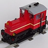
Hello, today I want to show some pictures of the V100 of DB colored red with gray stripes, this is how the machines looked like in the 1960ies. ... and from the other side, note that the doors are always on the left side of the cabin, so the ladders are different.... The model is in scale 1:45 (1:45,7 length, 1:44,1 wide, 1:43,6, height), total weight is 622gr incl. batteries. It is build on a normal 6/28 train base with 2x6 plates front and rear and a frame 1w around. The model is separated into different small moduls. Therefore you can easily take off the roof, detach the battery and remove the box. Here is a short video (35sec) showing the assembly But, most interesting: this loco can switch the next switch point remotely. I'll show this in a seperated thread. http://www.eurobricks.com/forum/index.php?showtopic=102050 cu Lok 24 Here's a link showing the original : http://www.bahnen-wu...nep-800-523.jpg
-
Hi all, I have shown the switch and the rails here last year: http://www.eurobrick...topic=79312&hl= and the original article with detailed instructions is found here: http://www.1000steine.de/de/gemeinschaft/forum/?entry=1&id=26244#id26244 Maik and David now improved the train very much, what can be seen in their video. cu Werner
-
Hi all, today I want to show you my level crossing, motorized by a medium-PF-motor. The intention was to move the bars slowly an synchronously. Therefore I used strings to drive the bars. There is a short video on youtube(50 sec): Here are some pictures of the house and the shed And here some pictures showing the technical details: on the left the gear, in the middle the cables and on the right the two bars the sliding bed, turnig the two liftarms allos you to adjust the cables the gear with the clutch mounting cables under the street and the rails and the two bars Hope you enjoyed this little project.... cu Werner
-
Yes, the Number is 4540381 , you can buy it for less than 1€
-
Hi Pierre, thanks for your interest. You are right, due to the clutch the motors are never stalled. Have a look at my point drive which uses the same technique: Please note that the point is not modified at all cu Werner
-
Luciano, if you plan with PF you just need one IR-Control+receiver (or two 9V-switches), one XL-motor to drive and one M-Motor to switch the gear, all other electric is obsolete. So this is very simple then, according to the picture I postet where you see all gears. Good luck! cu Lok24