

Glaysche
-
Posts
135 -
Joined
-
Last visited
Content Type
Profiles
Forums
Gallery
Everything posted by Glaysche
-
 It's been a long time since I've posted on here. I have still been making progress during this time. Most of my changes were inspired by new parts released by TLG. The first major change was inspired by this part on the new BMW motorcycle: This shock absorber has much higher travel than any of the other Lego shock absorbers so this would make a really good spring balance to improve axis 1 -- the main tilt axis on the bottom. Previous iterations of this design had used the shocks from the Unimog set. Those didn't prove to be that effective. This one was a little better. Here are the results: With the new spring balance, I was able to change the gearing on the axis to make it faster. It also got a bit smoother. This was the end of the major improvements on this version of the robot. To see it in its final form with a bunch more detail and freely available Studio file, see https://rebrickable.com/mocs/MOC-84097/glaysche/6-axis-robotic-arm/#details. The next big innovation came with this part: Upon seeing this part, I immediately knew I would want to use it to simplify and strengthen the "humerus". With it, I could make the attachment at the bottom much stronger and the whole thing simpler. Here is a comparison: The new one is on the right. This eliminates the spring balance (you'll see why in the next section) and most importantly, the connection at the bottom is 5L wide rather than 7L wide of the old one. This required me to redesign the shoulder component. To help with naming, this picture might help: This next version of the shoulder started as a blank canvas. I couldn't simply modify the old one to accept the narrower humerus. There were gears in the way and much of the geometry used frames that are not available in slightly smaller sizes. I did a lot of experimentation trying to fit the gear train into the smaller size and still be able to fit the gear train for the rotation axis (more on this in a bit). The real innovation came when I realized I could move the tilt motors to be closer to the tilt turntables. This ended up making the tilt axis much more powerful, smoother, and simpler. It was powerful enough that I no longer needed the spring balance which allowed me to simplify things even more. Here is a comparison of the old and new shoulder units: The new one is on the right. The high stress part of the gear train is similar to the old one but instead of going through a pile of gears to get to the two XL motors, I attached two large angular motors as close to the turntables as I could. This new gear train is much more efficient. Here is the comparison of functionality: It works much better without needing the spring balance. My next challenge was to make the rotation axis (axis 1) work better. The old rotation axis used 2 12t gears to drive the 60t turntable. That worked but it felt a little janky at high acceleration. I wanted to fit 4 12t gears around the turntable to get a more solid gear train for this high stress axis. I actually did find a way to fit all the gears into the shoulder for it wasn't braced very well. I had a limited amount of vertical space in the shoulder for gears. The next innovation was to put the gears for the rotation axis into the base rather than the shoulder. This allowed me to make a well braced gear train and put more structure into the shoulder to make it stronger and more rigid. I already talked about it a bit on @Jim's robot thread. I kept the motor in the shoulder and moved the gear train to the base. You can see the medium angular motor in the shoulder and 4 gears driving the turntable in the base. The power is transferred through an axle through the center of the turntable. Here is a cutaway of the gears: New version in its entirety: So how does all this work? Below you will find a video that combines the new version of the 6 axis robotic arm (https://rebrickable.com/mocs/MOC-109607/glaysche/6-axis-robotic-arm-mk-2/#details) and my 6 axis remote control (https://rebrickable.com/mocs/MOC-94286/glaysche/6-axis-remote-control/#details). They are connected together using Mindstorms hub to hub communications. You'll notice at the end of the video, the upper hub on the robotic arm crashes hard and stops responding. It has to be power cycled to use again. I'm pretty sure this is a bug in TLG's software, perhaps in the hub to hub communication. This bug has been there for the entire time hub to hub communications have been offered as a feature. Anyone know a good way to submit a bug report to TLG that they'll actually see and not just go into a black hole?
-
General Part Discussion
Glaysche replied to Polo-Freak's topic in LEGO Technic, Mindstorms, Model Team and Scale Modeling
It seems they are half pins with friction, now listed in the new Orchid set on Rebrickable: https://rebrickable.com/parts/89678/technic-pin-12-with-friction/72/ -
[MINDSTORMS] Big Robot v2
Glaysche replied to Jim's topic in LEGO Technic, Mindstorms, Model Team and Scale Modeling
I did actually buy two BMW sets for the parts. I used the 4 shock absorbers on the last version of my robotic arm and I’m planning to use the wheels and tires on a different MOC. -
[MINDSTORMS] Big Robot v2
Glaysche replied to Jim's topic in LEGO Technic, Mindstorms, Model Team and Scale Modeling
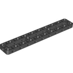
I agree. I only used them in my mockup because they were on top of the pile of parts... :) Yeah, I'm not sure. If it were really well supported so the sides can't splay apart, it might work. Maybe some triangles in the design holding the sides together. I had one other random thought. It seems like this is the perfect application for the new 3x19 frame: -
[MINDSTORMS] Big Robot v2
Glaysche replied to Jim's topic in LEGO Technic, Mindstorms, Model Team and Scale Modeling
I'm still pretty new at it myself. My first experience with Studio was making the model of the 6 axis robotic arm. I still very much prefer making things in real life first and just use Studio to document and share my creations. Given the big turntables you are planning, I don't think any design (within reason) will be too hard to turn. Another random idea I had was to have a single wheel per unit but drive it from the top. This is a quick mock up. I'm not sure if it can be properly braced or if the gearing would work out properly. The idea is to attach 36t gears solidly to the wheel and drive it with a couple 12t bevel gears. As much as possible, I try to have redundant gear trains in high stress applications to make things more solid. -
[MINDSTORMS] Big Robot v2
Glaysche replied to Jim's topic in LEGO Technic, Mindstorms, Model Team and Scale Modeling
Oh, by the way, you can use "rubber black" instead of "black" in Studio so the tires don't render so glossy. I'm not sure what the motorcycle hubs on the outside would attach to. If you are willing to go wider, you could use different hubs and do something like this: -
[MINDSTORMS] Big Robot v2
Glaysche replied to Jim's topic in LEGO Technic, Mindstorms, Model Team and Scale Modeling
Here is my new version of my robotic arm on Rebrickable: https://rebrickable.com/mocs/MOC-109607/glaysche/6-axis-robotic-arm-mk-2/#details It has a freely downloadable Studio file and a bunch of renders of the interesting bits. To finish the previous conversation, here are a couple renders of how the rotation axis works: I plan to do a writeup on my Eurobricks topic on this and my previous version but I want to get some videos and pictures first which may take me a while. -
[MINDSTORMS] Big Robot v2
Glaysche replied to Jim's topic in LEGO Technic, Mindstorms, Model Team and Scale Modeling
You can place them from the bottom of the base. You first bearing on the base, then snap the “shoulder” unit on. This engages the axle for the gear train. Finally, flip the whole thing over and reach in with relatively skinny hands and place the 2L beams. It’s a bit tricky and takes a couple tries but not too bad. I might be able to use longer beams that are easier to handle. I haven’t tried that. Thank you! -
[MINDSTORMS] Big Robot v2
Glaysche replied to Jim's topic in LEGO Technic, Mindstorms, Model Team and Scale Modeling
And thank you for the kind words. I was thinking this structure could make good shoulders for a humanoid robot. I haven’t shown off the tilt axis yet. It uses two large angular motors to drive 8x 12t gears around 2x 60t turntables which ends up being very smooth and powerful even under high load. -
[MINDSTORMS] Big Robot v2
Glaysche replied to Jim's topic in LEGO Technic, Mindstorms, Model Team and Scale Modeling
This is the interesting part of this new design. Normally, one would have a gear train in the upper part with the motor I didn’t have enough room up there. Instead, I put the gear train in the lower base and sent an axle through the middle of the turntable to turn the gears in the lower part. The gears in the lower part take power from the driving center axle and drives 2 gears, each of those drive 2 more gears which drive the 4 axles where the 12t gears are attached. Once I have a Studio model, I should be able to make a good rendering. hopefully, I can finish that soon. I ordered a bunch of those and the 20t gears while they were on Bricks & Pieces. I received them a little over a week ago. I don’t know where to get them now.. Note, for your application, I would put the gear train and motor that drives the turntable up in the body and not do the thing I described above. My main point is that I think you can make a really solid large turntable by just driving the 60t turntable in the middle with 4x 12t gears and the right gear train. -
[MINDSTORMS] Big Robot v2
Glaysche replied to Jim's topic in LEGO Technic, Mindstorms, Model Team and Scale Modeling
Here's a couple quick and dirty pictures: The top picture is of my robot base with the previously mentioned bearing. The gear train is in the base but the motor is in the unit that sits on top of that (bottom picture). I am using a medium angular motor as you can see there. The 98585 pieces you see there are attached to the output of the motor. I use that because it is a very rigid way to transfer torque. This setup acts a bit like a planetary gear. If you notice the blue pins is both pictures, when the two pieces are attached together, 2L beams are put on those pins to lock the 2 pieces together. This is critical in my application because when the arm is fully extended, it tries to pull this joint apart. Once I make the Studio file, I intend to put it up on Rebrickable for free download (like my last version of the robotic arm already is). -
[MINDSTORMS] Big Robot v2
Glaysche replied to Jim's topic in LEGO Technic, Mindstorms, Model Team and Scale Modeling
This is a very interesting topic I will be following closely. One thought I had is that, as you already mentioned, will be limited by the length of the wires on the PU motors. I worry in this case that the wires won't be long enough for the two motors attached to the wheels. As the wheels turn, the wires will twist together getting effectively shorter and stressing the wires. One thing I might explore is to put the drive motors in the chassis and send an axle through the turntable. This would allow unlimited steering rotation with no worries about the wires. The downside, of course, is that it certainly be less powerful than your proposed two motor design attached directly to the wheels. I wonder if the two motors may be overkill? One other thought on driving the steering. I have a similar design challenge with my 6 axis robotic arm. In my latest incarnation (which I haven't published yet), I found a way to fit 4 12t gears driving the 60t turntable in the middle. This ends up with a very solid feeling rotation axis that can turn a very heavy robotic arm using maximum acceleration on the motor. I did this instead of driving the outer ring because I am using a bearing similar to the one used in the Rough Terrain Crane which interferes with any gear on the outer ring. This makes disassembly and reassembly much, much easier than having a bunch of 1x1 round tiles as a bearing. -
Moving Mindstorms back to Technic
Glaysche replied to Jim's topic in LEGO Technic, Mindstorms, Model Team and Scale Modeling
As someone who has posted to both, I’m in favor. The distinction I drew when choosing the topic was mechanical things in Technis (even if it has a Mindstorms hub) and things about the software in Mindstorms. That distinction does feel arbitrary these days. -
General Part Discussion
Glaysche replied to Polo-Freak's topic in LEGO Technic, Mindstorms, Model Team and Scale Modeling
It looks like for the moment Bricks and Pieces has become a whole lot less useful: https://www.newelementary.com/2022/03/bricks-pieces-joins-pick-brick-new.html -
6 DOF robotic arm by Jos
Glaysche replied to Mr Jos's topic in LEGO Technic, Mindstorms, Model Team and Scale Modeling
You definitely can come up with a geometry with the BMW shocks that would allow a full 90 degrees of travel. It would be hard to predict how effective it would be without trying it. It takes a good amount of engineering to make the anchor points strong enough so they don’t flex too much which takes a lot of work. It looks like the counterweight system you have works pretty well so there’s not a lot of motivation to change it. I am really pleased with how well it worked on mine, however. It’s cool to see the different ways this problem can be solved. -
6 DOF robotic arm by Jos
Glaysche replied to Mr Jos's topic in LEGO Technic, Mindstorms, Model Team and Scale Modeling
@Mr Jos This inspired me to experiment with using the new large BMW motorcycle shock absorbers as a spring balance on my robotic arm. This enabled me to change the gearing to be faster. I think it works much better now. Here's a 27 second video showing before and after adding the spring balance. More details here. I like this solution because it is symmetric. The shock absorbers push the arm back to center when it goes both forward and backwards. It is also reasonably compact. Finally, when using PoweredUp / 51515, you are severely limited by the wire length for the motors and sensors so I couldn't use the hub as a counterweight. In fact, the exact locations of the hub are pretty much dictated by the lengths of the wires. -
New Elementary review: https://www.newelementary.com/2022/02/lego-technic-review-42141-mclaren.html
-
Thank you! Please do have a look. We can all learn from each other. Oh, speaking of that, you mentioned backlash in your most current design. That has been a challenge for me in my design. A few things have helped me. First, for long axles, it's often better to use connectors like 59443 or 42195. They are more rigid than axles. The second trick I've used is to have multiple redundant gear trains. You can then "pre-tension" the gear train by assembling it one or two teeth's worth of tension built in. That can dramatically reduce gear related backlash. Finally, I've found that by gearing down as late as possible in a gear train will reduce backlash. This keeps more of the gear train with lower torque. Any backlash in the low torque, high speed portion of the gear train is reduced by whatever gearing down you have at the end. I use this to drive the last two axes at the end of the arm. I actually gear up the motor for the long gear train, only to gear it down at the end.
-
Yeah: https://rebrickable.com/mocs/MOC-84097/glaysche/6-axis-robotic-arm/#details There was also a Eurobricks topic that's linked from the Rebrickable page.
-
Very cool. I like it. The 42100 is the set that pulled me out of my dark ages and sent me on my journey building my robot arm. Having seven motors to play with certainty begs you to make something like this. I ended up on a quest of iterative improvements every time I discovered new parts or new techniques that could help make it better. Have fun tinkering!
-
General Part Discussion
Glaysche replied to Polo-Freak's topic in LEGO Technic, Mindstorms, Model Team and Scale Modeling
Thank you, @Philo! I had never used PartDesigner before so it took me a little while to figure out how to add the connectivity and turn it into a Studio part. Here's my render for this use of the new shocks: Now if my B&P order would ever ship, I can try it in real life... -
Very cool to see all the components working together. I love it!
-
General Part Discussion
Glaysche replied to Polo-Freak's topic in LEGO Technic, Mindstorms, Model Team and Scale Modeling
I actually did order some of the BMW parts from B&P in the US almost a month ago. They still haven't shipped. They are usually slow but not this slow. I'm guessing the transition is causing a bunch of confusion at TLG. -
General Part Discussion
Glaysche replied to Polo-Freak's topic in LEGO Technic, Mindstorms, Model Team and Scale Modeling
Does anyone have a Studio part for 69633? I looked on @Philo's page (https://philohome.com/studio/packs.htm) and didn't find it. It's of course not in the official Studio release yet. Thanks!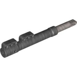
-
6 DOF robotic arm by Jos
Glaysche replied to Mr Jos's topic in LEGO Technic, Mindstorms, Model Team and Scale Modeling
Yeah, this was the trickiest axis for me as well. For quite a while, I used a spring balance to try to help the motor come up from the extreme positions. It never really worked that well because it needed very stiff springs to have any effect at all. Once I used stiff springs, friction and bending of the parts became a big problem. I ended up solving with brute force. The axis now uses two 60t turntables driven by 4 12t gears each. There’s a big gear train powered by two motors hard coupled together. It still creaks when extended to extreme positions but seems reliable. I’ve been thinking about using the new 1:5 scale extra long motorcycle front shocks which are longer and have more travel than any other shock. You could put these farther out on the arm to get better leverage and lower stress. Every design I’ve come up, however, with is super bulky so I haven’t pursued it further. Plus, my B&P order with more of them hasn’t arrived yet.