
SNIPE
-
Posts
2,678 -
Joined
-
Last visited
Content Type
Profiles
Forums
Gallery
Everything posted by SNIPE
-

General Part Discussion
SNIPE replied to Polo-Freak's topic in LEGO Technic, Mindstorms, Model Team and Scale Modeling
I wonder if the "teeth" on this part could act as an 8 position rachet by putting something that locks beetween the teeth but is on a rubber band so it can also skip to the next gap between the teeth: could be useful for paddle shift mechanisms etc. Regards, Snipe. -
42116 Skid Steer Loader
SNIPE replied to JintaiZ's topic in LEGO Technic, Mindstorms, Model Team and Scale Modeling
shame they discontinued those 3L worm gears. they have potential, because the other two worm gears might not fit in some rare circumstances. -
General Part Discussion
SNIPE replied to Polo-Freak's topic in LEGO Technic, Mindstorms, Model Team and Scale Modeling
same, we will get there one day :) -
General Part Discussion
SNIPE replied to Polo-Freak's topic in LEGO Technic, Mindstorms, Model Team and Scale Modeling
Thats genius ! -
General Part Discussion
SNIPE replied to Polo-Freak's topic in LEGO Technic, Mindstorms, Model Team and Scale Modeling
Did anyone notice the new track pieces (69900) I call them track with showspike I wonder if they just mesh with sprockets or if its more of a chain and needs gears Also they redesigned the axle hole with 4 bars (48723) so that its 1L thick now. The part number is 68888 And for wheel covers theres dish 4L (65138) but it has yet to exist in more useful colors for technic -
Great model. Is it possible to motorize the roof at all if I wanted to? (using a safety clutch)
-
General Part Discussion
SNIPE replied to Polo-Freak's topic in LEGO Technic, Mindstorms, Model Team and Scale Modeling
Best thing to do is look for the ldcad subfile of the rim without the tyre then get the diameter in LDU and convert LDU to mm. I used a ruler which is not very accurate but just the rim to me look lije its 46mm -
General Part Discussion
SNIPE replied to Polo-Freak's topic in LEGO Technic, Mindstorms, Model Team and Scale Modeling
Including the glued on tyre its 5.4cm this may be slightly off, but there abouts. -
General Part Discussion
SNIPE replied to Polo-Freak's topic in LEGO Technic, Mindstorms, Model Team and Scale Modeling
Spike prime wheel fits in a 42009 tire with no gaps :) -
Finally someone made it full RC and with two steering motors!. Any chance we can have instructions or a digital file?
-
I'm not sure why lego didnt use these two new pieces that came in the mario penguin These could be used for so many things such as body panels, spoilers, and body panels and body panels. Part IDs are 77095 and 77090
-
LEGO bricQ disgussion
SNIPE replied to SNIPE's topic in LEGO Technic, Mindstorms, Model Team and Scale Modeling
oh cool! -
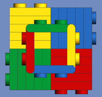
Hi, I just noticed two new sets from a new lego theme called BricQ, The great thing is it has a bunch of new recolors, here are the ones I found: Lime 7x11x1 frames Medium Azure 5x7x1 frames Medium Azure technic baseplate 11x19x1 Black weighted brick 2x6x2 Rare purple beams and red 3x11x1 panels Various new "old style" technic parts in new colors It includes pnumatics, mechanical technic parts and some system/semi-technic parts Here is a photo of the Bricq Motion Prime set: And here is a Here is a photo of the Bricq Motion Essential set: Regards, Snipe.
-
42128 - Heavy-Duty Tow Truck
SNIPE replied to Ngoc Nguyen's topic in LEGO Technic, Mindstorms, Model Team and Scale Modeling
because the diagrams for where each tube goes is always like a ball of spaghetti And they are unreliable and a pain to attach the hoses and a waste of space. -
42128 - Heavy-Duty Tow Truck
SNIPE replied to Ngoc Nguyen's topic in LEGO Technic, Mindstorms, Model Team and Scale Modeling
something like this, but better for 2021 would be cool, and no pnumatics! linear actuators and other mechanical mechanisms please! -
Nice parts usage and design
-
[WIP] Heavy Duty Skid-steer Loader
SNIPE replied to JLiu15's topic in LEGO Technic, Mindstorms, Model Team and Scale Modeling
nice work with the motors and wheel hubs. looks like a rollcage car -
42123 McLaren Senna GTR
SNIPE replied to Ngoc Nguyen's topic in LEGO Technic, Mindstorms, Model Team and Scale Modeling
As far as im aware there is no small new differential. -
General Part Discussion
SNIPE replied to Polo-Freak's topic in LEGO Technic, Mindstorms, Model Team and Scale Modeling
even a 2L crosa beam is useful because it acts like a purpendicular connector 2L but where both holes are pinholes. -
*ebays his regular grinder* Don't need that anymore :)
-
According to technicbricks the 2021 flagship is a CAT D11T https://www.facebook.com/groups/LEGO.Technic/permalink/4955027494569244/
-
General Part Discussion
SNIPE replied to Polo-Freak's topic in LEGO Technic, Mindstorms, Model Team and Scale Modeling
The same part is also available in lime for the creator tuplps. Updated my list -
General Part Discussion
SNIPE replied to Polo-Freak's topic in LEGO Technic, Mindstorms, Model Team and Scale Modeling
This part is still very useful because unlike using say two thin 2L beams and a 1x1 beam or bush, this is stronger and can be used as a 2L axle joiner. This part would also make a super useful crank shafs because the current specialised crankshaft parts while small allow the axle to slip out or bend slightly -
The gap between the left and right wheels is still the same, really the seperate chassis is just to show the idea of using the 1L beam with bionicle ball. The modded set also in the same file I need to build in real life to test out how to connect the R and L steering with the HOG.
-
Thanks for the LXF file, I have almost finished making it have 4 wheel steering, I also added 42115 diffs and mustang wheels. I am wondering it it is possible to replace the bulky ball and socket parts with something like this: and then there might be room for a center differenial. the small ball is jammed between two full bushes or (simular) parts. LXF FILE so far note* LDD wont let me place the mustang wheels over the black half frames but in real life it fits., Also the seperate chassis wheelbase is 1L too short but thats easily fixed.