doug72
-
Posts
2,426 -
Joined
-
Last visited
Content Type
Profiles
Forums
Gallery
Everything posted by doug72
-
 FINALLY got the ball transfer trolley to repeatedly traverse back and forth between load and unload points. Tried an attempt using levers and a trip bar to operate the change over mechanism but not reliable and often stalled when c/o stuck in the neutral position. Could’t get the trip levers to flip the red sleeve to alternate engage positions due force required to overcome the ridges on the drive sleeve. Modified a spare sleeve by filing off the small ridges which allowed trips to push the c/o red sleeve fully to engage gears but then tended to slip out again as trolley moved the other way. 2nd attempt abandoned ! Then I recalled my horizontal tower crane MOC which used friction pulleys and braided rubber cord to traverse the hoist trolley. Successful attempt: Using the proven c/o mechanism I made up a test rig as shown in the photos. The reversing output from the c/o drives a friction pulley used to drive the cord connected to the trolley carriage. After several gear combinations and pulley diameters arrived at a gearing that gave constant travel back & forth. The c/o unit continues to turn the drive pulley a bit more after the trolley hits the end stops (2lx4L lift arms). The two white 24T clutch gears are used back to back to form a pulley as they proved to be ideal diameter for the cord drive. The drive cord has to be adjusted to give just enough tension to move the trolley but be able to slip on the drive pulley when trolley reaches the end stops. Found Lego wedge pulleys tend grab the rubber cord and don’t allow it to slip. There is a dwell at each end of travel, to give time to auto load balls and then unload them. Next step is to postion the transfer track to about 30 degs and connect it to output from my Bucket Wheel ball lift. IMG_3561 by Doug Ridgway, on Flickr IMG_3563 by Doug Ridgway, on Flickr When all connected up to BW Ball Lift will post a video.
 -
The cam postion is very tight even after improving the one as shown in the video I thought I had found the fault in that I was taking the output to the rope drum from the crown gear wheel diven alternately by the change over c/o 16T & idler 16T gears so took the output from one of the idler gears driving the red axle instead. No improvemenst problem still there - I think its due to the inherrent lost motion in the change over clutch gears causing the output to advance slightly every cycle. The actual movement of the change over rod is very smooth and positive - problem lies in the c/o gear box lost motion Can't figure put how it seems to stay in sync in the video ! Going to try a c/o system that the trolley activates at each end of its travel by using a 32L axle with trips down the side of the ramp. Its try, try & try again until I succeed. Here's a couple of photos - the red axle is the output to the rope drum. IMG_3560 by Doug Ridgway, on Flickr IMG_3559 by Doug Ridgway, on Flickr Doug
-
Thanks DrJB & Captainowie: I am only using the first part of the mechanism i.e. the trolly up & down the ramp. The second part with the swinging arm will NOT be included - balls will travel on by gravity. I have tried many permutations including using a rack rail system with the gear on the trolley operated by a 32L axle & sliding 8T red gear to raise & lower the trolley with trips each end to reverse the rope drum, but did,nt work very well ! Rack system didn't work so reverted to a rope system. I will try to devise a gear system & drum diameter that allows easy changes to be made. The ramp will have an approx. 45 deg slope. Also found motor HAS to rotate in one direction only otherwise the arms moving the change over rod jam. To ensure motor only runs one way - stops prevent the battery box and PF switch from being push to the incorrect position. I'll post a photo of progress later.
-
I have reverse engineered the video and finally managed to get the reversing mechanism to work smoothly but now struggling to get the hoist drum to synchronise the trolly up & down the ramp. After every cycle the trolly shifts position gradually going one way until rope on the drum winds on the other way and the other way on the ramp. So far have not found a gear combination or drum diameter to keep the carriage in step repeatedly. Are there any instructions for this or does anyone know the gearing from the motor output to the rope drum - required to operate the trolly hoist so the travel back and forth is always the same and stays in sync. In the video unable to see the gear drive. Don't need the swinging arm to transfer the balls - they will just drop onto a chute to return the balls back to the Bucket Wheel Lift I have already built.
-
I used a Mk 1 control centre to operate my TC8 Tower Crane entry. Only problem I had is you need to ensure is that the end of memory sequence returns back at the same position as the starting point. Otherwise next time sequence is run its out of step especially the hoist and luffing rope drums which ended up in a tangle
-
[MOC] Bucket Wheel
doug72 replied to doug72's topic in LEGO Technic, Mindstorms, Model Team and Scale Modeling
For DrJb As per private message - images attached. Ball about to drop from bucket into conveyor hopper: The side ribs on the axle/bush connector (32039) help retain the ball until the drop zone: IMG_3548 by Doug Ridgway, on Flickr Conveyor: ball anti bounce lever. IMG_3547 by Doug Ridgway, on Flickr -
[MOC] Bucket Wheel
doug72 replied to doug72's topic in LEGO Technic, Mindstorms, Model Team and Scale Modeling
As requested :- Video close up showing ball release operating sequence: You Tube Video: [m.e.d.i.a.] [/m.e.d.i.a.]The Ball release lever & quadrant which rotate through 90 degrees. Trip lever turns this to transfer the ball which rolls down into the bucket. Quadrant prevents next ball from moving until counterweight returns the ball release to the ball loading position which limited by a stop. IMG_3534 by Doug Ridgway, on Flickr Ball ready to be released by operation of trip lever. IMG_3535 by Doug Ridgway, on Flickr Quadrant holds back next ball. IMG_3536 by Doug Ridgway, on Flickr Side view showing trip lever and push rod / cranks. IMG_3537 by Doug Ridgway, on Flickr Camera holder: IMG_3539 by Doug Ridgway, on Flickr -
[MOC] Bucket Wheel
doug72 replied to doug72's topic in LEGO Technic, Mindstorms, Model Team and Scale Modeling
Took a lot of experimenting to get it to work correctly every time to drop a ball into a bucket. Projections on the wheel rim hit a trip lever which operates the ball release - a counterweight returns the ball release to allow next ball to roll onto the "L" lever ready for the trip arm to release it. As the "L" arm rotates 90 degrees the 1/4 quadrant stops any more balls from moving. 3:1 step up gears are used to get desired operating speed. Once ball releases it rolls down a short ramp to drop into the bucket. The ball release mechanism can be seen operating in the video in my previous post. I will make a larger close up video later plus parts required to make it. First attempt saw ball transfering OK into the bucket but as the counterweight returned the "L" shape 3 x 3 thin arms to pick up the next ball it tended to flick it back up the entry slope. The ball then didn't enter the release mechanism until next cycle and only if it had to have other balls behind it to push it in. -
[MOC] Bucket Wheel
doug72 replied to doug72's topic in LEGO Technic, Mindstorms, Model Team and Scale Modeling
Finally devised a reliable marble ball transfer system for loading balls into each bucket as the wheel rotates. Bucket wheel operates a trip lever and cranks to release one ball at a time - while holding the next ball until next bucket arrives. Marbles drop from the conveyor onto guides which returns the balls back to the start. Lego roofing bricks make good ball guides. General View of Bucket Wheel ball lift. IMG_3529 by Doug Ridgway, on Flickr Close up of ball transfer station with ball ready to be launched into the next bucket. IMG_3525 by Doug Ridgway, on Flickr Close up showing how the quadrant stops the ball behind from moving unitl the next bucket come along. IMG_3526 by Doug Ridgway, on Flickr Video of Bucket Wheel Lift in motion. MVI_3533 by Doug Ridgway, on Flickr -
[MOC] Bucket Wheel
doug72 replied to doug72's topic in LEGO Technic, Mindstorms, Model Team and Scale Modeling
Progress is slow ! The actual ball release is simple - just a pair of 3L x 3L thin lift arms placed between the guides the balls roll along. As this rotates 90 degrees it allows one ball at a time to pass but stops any balls behind it moving until the next cycle. Had hoped to link this movement by a gearing arrangement linked to the bucket wheel rotation. For one revolution of the bucket wheel the ball release has to operate 8 times meaning an 8:1 step up gear box linked to a crank arms that rotate the lift arms. Only way to get 8:1 step up was to use three stage 2:1 step up gears ( 2 x 2 x 2 = 8 ) but didn’t work when connected to crank arm due to too much friction. Finally gave up on that and went for a trip lever system. Bucket wheel re-designed using 8 each # 2 & 4 connectors making an octagonal bucket wheel The 8 spokes connect to the 8 hole hub with # 1 connectors and with # 6 connectors at the rim. Spoke are 8L and arranged at an angle, and has no tendency to twist. The # 6 connector at the rim allows a fixing point for the trip rollers which as they pass move an arm linked to the ball release via two 3L crank arms, a push rod and a 3:1 step gears up to rotate the ball lift arms the required 90 degrees. A counterweight arm resets the ball release after trip lever disengages from each trip roller allowing next ball to enter the trip arm. Trying to synchronise this is the headache - to get balls to roll down the track and into a bucket. Nearly there just a bit more tweaking required. Had hoped to load balls at a low level but balls tend to catch on the lip of the bucket so have had to raise the loading point for drop balls in without bouncing out again. As I don’t have any Lego balls have substituted glass marbles ! Images hopefully will make this clearer. IMG_3517 by Doug Ridgway, on Flickr IMG_3516 by Doug Ridgway, on Flickr The two rollers in this image should have rubber tires like the others - none left in my parts box. -
[MOC] Bucket Wheel
doug72 replied to doug72's topic in LEGO Technic, Mindstorms, Model Team and Scale Modeling
Which is why I asked Efferman to design an 8 hole hub, now available at Shapeways:- https://www.shapeway...d&utm_content=2 Have designed a ball release mechanism to release one ball at a time into a bucket - just need to figure out how to syncronise the ball dropping as each bucket passes. -
Tiny MOC Collection
doug72 replied to JDL1967's topic in LEGO Technic, Mindstorms, Model Team and Scale Modeling
A tiny forum post for a tiny subject !! -
[MOC] Bucket Wheel
doug72 replied to doug72's topic in LEGO Technic, Mindstorms, Model Team and Scale Modeling
Built up bucket wheel using # 2 and #4 connectors with radial 4L spokes with 8 hole dish - 5L Diam. The centre hub is stable. Only two buckets shown but would accomodate 8. Each spoke has 1 x #1 connector and 1 x axle /bush connector. IMG_3509 by Doug Ridgway, on Flickr IMG_3510 by Doug Ridgway, on Flickr Marble run machine (MOC) progress to date:- Some images of the marble run machine I am attempting to build. Bucket wheel driven by L motor with 72:1 reduction. Conveyor is driven by M motor with 1:1 drive. Next step is to find a satisfatory way to pick up marbles in the buckets. Its hand loaded at the moment. IMG_3511 by Doug Ridgway, on Flickr IMG_3512 by Doug Ridgway, on Flickr IMG_3513 by Doug Ridgway, on Flickr IMG_3514 by Doug Ridgway, on Flickr IMG_3515 by Doug Ridgway, on Flickr -
[MOC] Bucket Wheel
doug72 replied to doug72's topic in LEGO Technic, Mindstorms, Model Team and Scale Modeling
For radial spokes to work they need to have a rigid connection at the hub end. Did a test with an enlarged diamenter rim wheel with 8 hole dish using radial spokes but the dish tends to twist relative to the rim as it turns. I,m satisfied with the wheel and hub with with angled spokes. -
[MOC] Bucket Wheel
doug72 replied to doug72's topic in LEGO Technic, Mindstorms, Model Team and Scale Modeling
Hi Efferman. Brought two 8 hole dish, 5L diam. on extended delivery (cheaper postage) but arrived in just over a week. Pin holes all OK. Cross Hole: one appeared to be blocked but just loose dust from the flexible polishing. One unit X hole a firm fit on axle the other slightly slack but OK if add 1L bush each side. No problem with your design - just need shorter axle (4.5L) to have straight spokes but works OK with spokes angled as shown in images. Also brought a set of train rollers and these are OK now with cross hole clear and not too tight a fit. I use a Lego threaded axle to clean out the cross holes of any detritous from the 3D process. -
[MOC] Bucket Wheel
doug72 replied to doug72's topic in LEGO Technic, Mindstorms, Model Team and Scale Modeling
The wheel discharges onto the conveyor p/n 4597139 from the 4645 harbour set. Wheel & conveyor have seperate motors. Next challange is to figure out how the bucket picks up balls ( I'm using glass marbles for now to test it). Return to collecting box will be via series of switch backs. I'll post some images as the MOC progresses. -
[MOC] Bucket Wheel
doug72 replied to doug72's topic in LEGO Technic, Mindstorms, Model Team and Scale Modeling
Plenty of options for 6 spokes but none I could come up with for 8 spokes using Lego part for the centre hub. hence 3D printed disc by Efferman for me. -
[MOC] Bucket Wheel
doug72 replied to doug72's topic in LEGO Technic, Mindstorms, Model Team and Scale Modeling
Thanks for the idea, just tried that and they are too short by 0.5L !! Wheel is 16L diam. - Hub is 5L so for radial spokes they need to be 5.5L = axle 4.5L plus 2x #1 connectors. Could cut 9L axles in 1/2 but don't like doing that. Some old water wheels had spokes arranged like this. Have tried other combinations of angled connectors but the the # 3 gives best result. -
My attempt at making a bucket wheel. Bucket Wheel is built using 8 pce. LEGO White Visor 2007 (57702) Wheel rim is made from 16 pce. # 3 connectors. Centre Hub: Efferman 8 hole dish, 5 stud diameter. Spokes at an angle using 5L axles - to have radial spokes would require a 4.5L axle which not available. At the moment intend use this either for a first attempt at a GBC or for a Bucket Wheel Trencher machine. IMG_3508 by Doug Ridgway, on Flickr IMG_3507 by Doug Ridgway, on Flickr
-
Mine brought On Amazon. http://www.amazon.co.uk/LEGO-Power-Functions-Idea-Book/dp/1593276885
-
For examples of an M motor driving steering racks see Toshihito Isogawa Lego Power Functions Idea book: Machines and Mechanisms:- Part 1:- Rack and Pinion Gears - pages 114 to 823. I got both of his books for Xmas and they are a fantastic source of solutions for Technic mechanisms.
-
Gears Meshing at 'other' angles
doug72 replied to DrJB's topic in LEGO Technic, Mindstorms, Model Team and Scale Modeling
For examples of gears meshing at different angles see Toshihito Isogawa Lego Power Functions Idea book: Machines and Mechanisms:- Part 1:- Tilting the Angle of the axle - pages 84 to 89 I got both of his books for Xmas and they are a fantastic source of solutions for Technic mechanisms. -
Efferman's Custom Parts
doug72 replied to efferman's topic in LEGO Technic, Mindstorms, Model Team and Scale Modeling
Efferman, Many thanks - that's exactly what I need. Also useful for making ferris wheels and fairground rides. Once price is known will be ordering with next batch of 3D parts from Shapeway. -
Efferman's Custom Parts
doug72 replied to efferman's topic in LEGO Technic, Mindstorms, Model Team and Scale Modeling
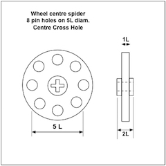
Efferman: Can you design an 8 hole wheel hub spider as per drawing. Can be either plain circle or 8 arms each with a pin hole to reduce 3D material used. Pin hole equally spaced on 5L diam. / Centre cross hole. This is for building a small bucket wheel for a MOC of a BW trencher.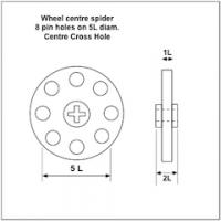
-
Took me a while going through all my Lego instruction books to find the part - it was in the last one I looked - Mars Misson 7645 set mining vehicle. Your use of the scoops has inspired me to use them for a medium size bucket wheel trencher. So far have made the bucket wheel but only has 6 scoops - more on order as the BW will require 8. Wheel rim made up of 16 pce. # 3 connectors with a diameter of approx. 16L. The discharge will use the conveyor from the Lego City 4645 harbour set with wheel and conveyor motorised. I will start a new topic once there is more progress on this MOC.