

PlanetaryHub
-
Content Count
20 -
Joined
-
Last visited
About PlanetaryHub

Recent Profile Visitors


-
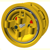
Planetary Wheel Hub - Please Help
PlanetaryHub replied to PlanetaryHub's topic in LEGO Technic, Mindstorms, Model Team and Scale Modeling
Last "Easter Holidays" video just posted on YouTube - enjoy: -
@deraven Thanks. I guess, if Lego have no official name, it can be referred to as the "Ø1.5mm shaft & socket connector system" without confusion?
-
Planetary Wheel Hub - Please Help
PlanetaryHub replied to PlanetaryHub's topic in LEGO Technic, Mindstorms, Model Team and Scale Modeling
Driving the planetary hub directly with an XL motor does give a lot of torque due to the 3:1 step down. As you suggest a slightly larger scale model (longer track) would probably be better - the video was just intended to be fun. -
Planetary Wheel Hub - Please Help
PlanetaryHub replied to PlanetaryHub's topic in LEGO Technic, Mindstorms, Model Team and Scale Modeling
New track test rig video just uploaded to YouTube: -
Please could someone tell me what the correct Lego terminology is for the cylindrical sockets and pins used to attach mini figure accessories, for example a feather to a crown: Thanks.
-
Planetary Wheel Hub - Please Help
PlanetaryHub replied to PlanetaryHub's topic in LEGO Technic, Mindstorms, Model Team and Scale Modeling
@Dafgek81 Thanks for your interest, I will keep you posted - another video is on the way and will be uploaded shortly... @JJ2 Thanks for your feedback, one solution is to add a hub cover: -
Planetary Wheel Hub - Please Help
PlanetaryHub replied to PlanetaryHub's topic in LEGO Technic, Mindstorms, Model Team and Scale Modeling
Yes, on real world parts the hub internals are hidden by a cover that forms part of the rim assembly. However with these parts I was keen to maximise their educational value and therefore decided to leave the planet carrier exposed and also provide a good view of the gears in action by peppering it with holes! Nonetheless they are close in design to real world parts and work in an authentic way, this allows realistic functional models to be built. -
Planetary Wheel Hub - Please Help
PlanetaryHub replied to PlanetaryHub's topic in LEGO Technic, Mindstorms, Model Team and Scale Modeling
A new video for your delectation... -
Planetary Wheel Hub - Please Help
PlanetaryHub replied to PlanetaryHub's topic in LEGO Technic, Mindstorms, Model Team and Scale Modeling
Just for fun, while Shapewaiting, I have uploaded a short animated video of a track loop running on two planetary hubs: https://www.youtube.com/channel/UCRxfS08NGOt0pCMtIKLkLXg -
Planetary Wheel Hub - Please Help
PlanetaryHub replied to PlanetaryHub's topic in LEGO Technic, Mindstorms, Model Team and Scale Modeling
Thanks for the information efferman! No, my CAD holes are circular -
BrickWarriors Jan 2016 - New Steampunk Pieces!
PlanetaryHub replied to Thrash's topic in Minifig Customisation Workshop
I like the detail on the trench coat, very good. -
Planetary Wheel Hub - Please Help
PlanetaryHub replied to PlanetaryHub's topic in LEGO Technic, Mindstorms, Model Team and Scale Modeling
1) Is my CAD orientation correct: hole axis = z-axis? 2) I assume my CAD dimensions are OK...? -
Planetary Wheel Hub - Please Help
PlanetaryHub replied to PlanetaryHub's topic in LEGO Technic, Mindstorms, Model Team and Scale Modeling
@efferman 1) How do you know which way up Shapeways will print an item? I had the impression that they rotated parts to optimise use of the printer's material box, i.e. packing as many parts in as possible with no guaranteed orientation...? 2) I have found the test part that I printed at Shapeways!: It is a 1M long version of the standard 2M Tube Coupler ( http://brickset.com/parts/4526985 ) and probably similar to the 1x1 Beam ( http://brickset.com/parts/6100030 ). The part's cylindrical axis is parallel to the z-axis in the stl file and it was printed in unpolished strong & flexible. LEGO axles will fit in the bore, but rotate with some friction. LEGO friction connector peg's will also go in, but are very tight. The dimensions compare as follows: [mm] CAD Actual Outside Diameter 7.80 7.76 Bore Diameter 4.90 4.75 Overall Length 7.80 7.96 Any thoughts on why the bore & overall length are not closer to the CAD dimensions? Thanks. -
Planetary Wheel Hub - Please Help
PlanetaryHub replied to PlanetaryHub's topic in LEGO Technic, Mindstorms, Model Team and Scale Modeling
@efferman Thank you for your help. 1) Just to confirm that I have understood you: if I had an 8.0mm diameter rod, it would need to be in a 8.6mm diameter hole to rotate freely...? 2) Do you just use unpolished nylon? Is this to avoid the dimensions changing unpredictably during polishing? 3) Last year I did print off a small test part in nylon at Shapeways (added to an order for something else not LEGO related). The CAD file had a 4.9mm diameter hole, but the hole in the actual part was smaller. When I find the test part, I will post the actual dimensions. If this discussion is boring everyone else, I could revert to PM's - let me know. -
Planetary Wheel Hub - Please Help
PlanetaryHub replied to PlanetaryHub's topic in LEGO Technic, Mindstorms, Model Team and Scale Modeling
@efferman Your Technic parts on Shapeways look great. Please can you help me with some advice on correct tolerancing for printing successfully in fused nylon (strong & flexible) at Shapeways?