Imanol Posted April 2 Posted April 2 Hi, After just finishing the S-130 Project I´ve already decided to start a new one. In this case this is going to be the Renfe Class 309, a small 3 axle shunting locomotive from the 1980s. This quite a big contrast with the S-130 but I think is a perfect little project. This is the train in question: The main challenge on this project is how to power it, in this case I´m thinking about using Circuit Cubes to power the three axles. For the running gear design I decided to based it in the one made by @jtlan for his TP56 Switcher Locomotive as is one of the only examples of a 3 axle shunter that I found. Even with this base as a starting point is not easy to do this as my design is just 7 stud wide so I need to offset everything. This is a rough assembly that I have done for now: As it can be seen, the motor will be placed on the front and the battery is going to be right behind, the idea is to use them as counterweight for the heavier cab which is located on the rear just behind the last axle. And now it comes the part in which I ask for some help: Even though I have the design mostly figured out (I might need to make a prototype to see if it can work through R40 curves) my main concern is with the Circuit Cubes Motor and their power output and speed. This is a shunting locomotive so it´s not going to be as fast as the S-130 but even then, it seems that they are quite slow and might require a 1:2 gear ratio which can be simply added onto this design. My concern with this is that is going to become severly underpowered and wont be able to pull any load. I´m not expecting to pull something as massive as the S-130 cars but I would love for it to be able to maybe pull at least one of the passenger train cars that I´ve already designed (although I´m not planning on building them any time soon). This cars are massive with a weight of 1kg each, but those were the real load for this locomotive on the past. I´ve already tinkered with the idea of adding two motors but that will require a much complex redesign as I need to keep the middle axle powered through a worm screw to make it able to work through R40 curves. In this case I think there is enough interior space for me to not worry about it: I would like to know if anyone has done a proper test of the Circuit Cubes motors and knows their maximum load and speed. For now I´m going to continue working on the one motor design and make plans to order pieces for a small prototype. Imanol Quote
Shiva Posted April 2 Posted April 2 Nice! But, for me, it looks like you are blocking the mid axle from moving? if comparing to jtlan's design. Quote
zephyr1934 Posted April 3 Posted April 3 It looks great... 18 hours ago, Imanol said: Even though I have the design mostly figured out (I might need to make a prototype to see if it can work through R40 curves) my main concern is with the Circuit Cubes Motor and their power output and speed. This is a shunting locomotive so it´s not going to be as fast as the S-130 but even then, it seems that they are quite slow and might require a 1:2 gear ratio which can be simply added onto this design. My concern with this is that is going to become severly underpowered and wont be able to pull any load. I´m not expecting to pull something as massive as the S-130 cars but I would love for it to be able to maybe pull at least one of the passenger train cars that I´ve already designed (although I´m not planning on building them any time soon). This cars are massive with a weight of 1kg each, but those were the real load for this locomotive on the past. ... but yes, it will be slow, or under powered, or both. I have a great little circuit cube steamer, stepped it up 3:1 so that it would move at an okay speed and it stalls with more than two light cars (plus the tender), all with ball bearing wheels. Quote
Imanol Posted April 3 Author Posted April 3 14 hours ago, Shiva said: Nice! But, for me, it looks like you are blocking the mid axle from moving? if comparing to jtlan's design. Wow, you are right. I added those thin liftarms brackets without realising that they were blocking the central axle movement. I will need to redesign the attachment to the main body. 2 hours ago, zephyr1934 said: It looks great... ... but yes, it will be slow, or under powered, or both. I have a great little circuit cube steamer, stepped it up 3:1 so that it would move at an okay speed and it stalls with more than two light cars (plus the tender), all with ball bearing wheels. Thanks, I think I captured the real design quite well. Yeah, I already imagined that is going to be the problem. I´m hoping that maybe having three powered axles with friction bands might at least improve the pulling power. At the same time I saw someone using it to power the orient express with multiple coaches with just one motor. The slower speed I think I can take it, but I would like to have at least some pulling power. Imanol Quote
idlemarvel Posted April 4 Posted April 4 Another great model from you, thanks for sharing. I have a Circuit Cube motor, but I have only tried to run small narrow gauge trains and even then they struggled to pull a single coach around curves, but these were the narrow gauge R24 curves. Have you thought about the "mini-Hub" option? You remove the 6xAAA battery holder, unsolder the battery holder leads, 3D print a new base and you end up with a Powered Up hub that is 4x8x1 1/3 (4 plates high). If you turn it on its side it is effectively 2x8x3 1/3 (10 plates high). You could fit that and the 9V battery and a PUP motor somewhere in the body of your loco, I would have thought. This is what I mean: I realise this is not purist Lego, but neither is using Circuit Cubes! If you take care you can restore the hub back to its original state. Quote
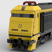
Imanol Posted April 4 Author Posted April 4 I´ve been working more on the project and I have a better design that I think could work. I also decided to make renders instead of screenshots as they allow to see detail much better. With a small modification I´ve been able to fit the motor and the battery in the front hood: The motor needs to be sideways as that way I can connect it to the rest of the body without changing the gear ratio. At the same time the battery can´t be moved inside the cab due to the amount of brackets and supports that are required for each angled piece so there is no easy way of adding a second motor. I have also reworked the attachments from the technic frame to the body and now there is nothing that impedes the swivel of the middle axle: I´ve tested this design in real life and I´ve confirmed that it can run fine on R40 curves and that the couplers can also follow the same trajectory. At the same time I also took the opportunity to see if the tiles that cover the wheels had any issue with the swivel axle and I´ve confirmed that is also fine. For now, the mechanism is designed to be used with a 1:1 gear ratio of 16 tooths gears. In theory could me modified for 1:3 ratio but the 24 tooth gear doesn´t fit currently. So for now this is all the progress I´ve made, I´m still going to look how to maybe change the gear ratio as I might prefer something a little faster and I will also look at ways of improving the fitment and attachment of the components, specially the motor as right now is not very secured. 1 hour ago, idlemarvel said: Another great model from you, thanks for sharing. I have a Circuit Cube motor, but I have only tried to run small narrow gauge trains and even then they struggled to pull a single coach around curves, but these were the narrow gauge R24 curves. Have you thought about the "mini-Hub" option? You remove the 6xAAA battery holder, unsolder the battery holder leads, 3D print a new base and you end up with a Powered Up hub that is 4x8x1 1/3 (4 plates high). If you turn it on its side it is effectively 2x8x3 1/3 (10 plates high). You could fit that and the 9V battery and a PUP motor somewhere in the body of your loco, I would have thought. This is what I mean: I realise this is not purist Lego, but neither is using Circuit Cubes! If you take care you can restore the hub back to its original state. I don´t mind doing something that is not pure LEGO in cases like this, but unfortunately the space inside the train is very limited and knowing how much effort took to fit the PU motor in my previous train even when that was much bigger, I don´t think is even possible to make room for all of this. As I´ve mentioned in this same post, the cab space is not available due to the brackets and supports of the curved pieces that form the rear and front with the same happening in the front of the hood. In any case, I might revisit some ideas like this as at some point I want to build some multiple units passenger trains, and as with all of my designs, I don´t want to remove any interior detail to make room for a full powered up hub. In fact, my (crazy) idea was to use circuit cubes for that, but knowing their limitations I think I might need another design. Thanks for all the help and ideas, Imanol Quote
Thomas Waagenaar Posted April 4 Posted April 4 (edited) The exterior looks really nice! But I'd recommend getting rid of those worm gears. The circuit cubes are slow with 1:1 gearing at 160rpm. You're gearing them for 20 RPM... It'll feel like it's not moving at all 😬 Edited April 4 by Thomas Waagenaar Quote
Imanol Posted April 4 Author Posted April 4 23 minutes ago, Thomas Waagenaar said: The exterior looks really nice! But I'd recommend getting rid of those worm gears. The circuit cubes are slow with 1:1 gearing at 160rpm. You're gearing them for 20 RPM... It'll feel like it's not moving at all 😬 Thanks, I didn´t think about the gearing on the worm gears, is there any exact formula to calculate it? I can change it for bevel gears but I feel the swivel axle is not going to work the same, I checked and it looks like it might require an entire redesign as the current design has the longitudinal axle over the main axles. Anyway, I will start looking for a better solution Quote
Shiva Posted April 4 Posted April 4 Hmm, that Circuit Cubes, ain't it only a battery? Or is it a place holder for the Bluetooth Battery Cube? That 30413 Panel, makes it look like a placeholder. For gearings Sariel has a calculator https://gears.sariel.pl/ Quote
Imanol Posted April 4 Author Posted April 4 22 minutes ago, Shiva said: Hmm, that Circuit Cubes, ain't it only a battery? Or is it a place holder for the Bluetooth Battery Cube? That 30413 Panel, makes it look like a placeholder. For gearings Sariel has a calculator https://gears.sariel.pl/ The circuit cube is the only battery that is available in LDraw, in reality is supposed to be the bluetooth battery cube but it´s something that I don´t even mind as is just used to check the fitment. The 1x4 panel is put there to account for the cable connections as I don´t want to have any problems of bending the cable more than it should. I have already used the Sariel calculator but I didn´t realize that the worm gear was in there. I will need to look for a better design that will still allow for the swivel of the middle axle Imanol Quote
Shiva Posted April 4 Posted April 4 Yeah, that Panel should be good for the cables :) Better design needed? jtlan uses a 9V motor, that is geared down from a Technic Bush 1/2 Smooth to a Wheel with Split Axle Hole with a belt. I'm not sure, but it could be in the range of 3 to 1? If checking https://www.philohome.com/motors/motorcomp.htm that motor has rotations speeds from 580rpm at 4V, to 3300rpm at 12V. 9V 2200rpm. So at max it would be around 1100rpm to the driveshaft and 137,5rpm to main axle? Torque, way less than Cubit Motor Cubes. and what rpm shown on video, not known. Cubit Motor Cube 160rpm or thereabouts? Right now, it looks like you have 1 to 1, so 160 rpm? to Here's a video of Cubit Motor Cube with Orient Express Direct drive to L wheels "30.4mm" 95,5mm circumference. Ok, I'm impressed by its strength! So if that Orient express could go 160rpm, with 95,5mm, that would mean 15,28meters / minute? theoretically. You use 55423c01 "17,6mm diameter" circumference 55,29mm. 160rpm at engine and driveshaft. Gear ratio 8 to 1. So 20 rpm That gives 1 105,8mm. So, 1,1meters / minute. Unless I counted wrong somewhere? You have the torque, while the speed itself would be, slow. What you can pull, would be decided of the weight of the shunter and not the Cubit Motor Cube. How fast? that would depend on the gearing you can get. Quote
Shiva Posted April 4 Posted April 4 (edited) Hmm, what if axle distances were changed to prototypical distance? https://www.listadotren.es/carac/fichadatos.php?id=11 Why am I linking this? What if, it could be possible to get space enough, to install the Cubit Motor between the axles and trying to drive it with one powered axle, as an option, similar to the Orient Express locomotive? Or, would the space still be, not enough? If using Axle distances as scale, then moving the middle axel 1 stud forward, would only be a 8cm deviation of IRL. And that should give enough space to use the technic used for the Orient Express locomotive with a Cubit Motor. Either on the middle "lateral" axle or the rear axle. But, this would mean 1 driving axle of 3. Well, same as the Orient Express loco. Is that enough for a shunter? One plus would be, more space for extra weights. Yeah, I, have spent hours to check these things out. Edit, seems the reddit links from previous post do not always show up? So, here the links in text format. https://www.reddit.com/r/LEGOtrains/comments/1q3b0uv/orient_express_powered_by_a_single_circuit_cube/ and https://www.reddit.com/r/LEGOtrains/comments/1q3cfb4/how_to_power_the_orient_express_with_circuit_cubes/ It could be that I have counted some distances needed incorrect, due to not having a Cubit motor. Yep, I am forgetting that the Cubit would block half of a driving axle... if it was placed between the axles. One solution could be to have the Cubit and axle point down? If 1:1 drive to one axle and/or driveshaft. Another Edit: I counted on the Orient Express loco axle distance, instead of the 309's prototypical. Cubit would fit between B-C axles, but it would be too close to the rails. As in, it could/would? hit the lead rails on a railroad switch. Edited April 5 by Shiva Quote
Imanol Posted April 5 Author Posted April 5 14 hours ago, Shiva said: Hmm, what if axle distances were changed to prototypical distance? https://www.listadotren.es/carac/fichadatos.php?id=11 Why am I linking this? What if, it could be possible to get space enough, to install the Cubit Motor between the axles and trying to drive it with one powered axle, as an option, similar to the Orient Express locomotive? Or, would the space still be, not enough? If using Axle distances as scale, then moving the middle axel 1 stud forward, would only be a 8cm deviation of IRL. And that should give enough space to use the technic used for the Orient Express locomotive with a Cubit Motor. Either on the middle "lateral" axle or the rear axle. But, this would mean 1 driving axle of 3. Well, same as the Orient Express loco. Is that enough for a shunter? One plus would be, more space for extra weights. Yeah, I, have spent hours to check these things out. Edit, seems the reddit links from previous post do not always show up? So, here the links in text format. https://www.reddit.com/r/LEGOtrains/comments/1q3b0uv/orient_express_powered_by_a_single_circuit_cube/ and https://www.reddit.com/r/LEGOtrains/comments/1q3cfb4/how_to_power_the_orient_express_with_circuit_cubes/ It could be that I have counted some distances needed incorrect, due to not having a Cubit motor. Yep, I am forgetting that the Cubit would block half of a driving axle... if it was placed between the axles. One solution could be to have the Cubit and axle point down? If 1:1 drive to one axle and/or driveshaft. Another Edit: I counted on the Orient Express loco axle distance, instead of the 309's prototypical. Cubit would fit between B-C axles, but it would be too close to the rails. As in, it could/would? hit the lead rails on a railroad switch. I had already thought about using the correct wheel spacing of the real locomotive, but it doesn't work well with the technic frame. The Orient Express uses rods to transmit the power to the other wheels so even if the motor is only connected to one axle, the power is transmited to the other ones. There is ways of using a 1:1 gear ratio inside the frame, the main problem is getting the middle axle to swivel. In anycase, thank you very much for the ideas and the effort. Unfortunately I don't have access to Studio today so until tomorrow I can't test anything Imanol Quote
Shiva Posted April 5 Posted April 5 Blind drivers for the middle axle could maybe have made it easier. Quote
Imanol Posted April 6 Author Posted April 6 15 hours ago, Shiva said: Blind drivers for the middle axle could maybe have made it easier. I thought of that but apparently no one builds them for that size as they are usually used on Steam Locomotives which use bigger size wheels. After thinking carefully I decided to broad my search to include three axle bogies on locomotives and I found some promising leads. There is one design that can be easily adapted onto mine and that the only compromise that it has is that the middle axle is unpowered. It also has a gear reduction but is much more manageable: Bogie 3 axle - with floating mid-axle. From what I´ve seen this is one of the most used solution, usually combined with a 2x2 round plate or tile that acts as a blind driver, although I will prefer keeping a real wheel on the middle axle. I also thought about going back to a more realistic axle layout, but the main problem is that it needs to have the same footprint, as in the front and rear of the locomotive there are two tanks that are 1x2 so the wheels can´t be put behind them. To be honest, the main problem with that layout is that is not technic compatible as it has a wheel offset by 1/2 technic pin so it´s going to be a pain to make a strong frame for that. For now I will try and see how difficult is to implement a 2 axle powered design and see if it might be enough. Thanks, Imanol Quote
Imanol Posted April 6 Author Posted April 6 Okay, I´ve been working on the new design and fortunately it was very easy to implement into the previous frame. I was worried that moving the motor backwards would require to make room on the cab for the battery but I was able to just move it to the front: I was also able to found the correct ldraw file for the Bluetooth Battery although it really doesn´t matter. The biggest challenge with this design is making it able to attach to a odd number chassis but I think this solution is strong enough and allows me to keep the same attaching points: Lastly, this design contains a gear ratio of 1:1.67 (from 20 tooth to 12 tooth) which I think is more acceptable: I also overdid the connection for the 20 tooth gear using the 39793 technic connector as this was a big problem on my other train design. I would love if someone is able to spot any problems with the design to please tell me, although I think that this time I did my work. This is all I have for now. Imanol Quote
CastleRail Posted Monday at 08:56 PM Posted Monday at 08:56 PM Just one minor point - how are you going to get the cube out for charging? The socket is on the edge next to the motor and you appear to have fixed it in position on brackets. So long as it can't move to foul the gears you could remove the brackets and have it loose? Quote
Shiva Posted Monday at 08:58 PM Posted Monday at 08:58 PM Trixbricks has blind drivers for LEGO sizes. https://trixbrix.eu/en_US/p/Train-Wheel/843. Looks good. remember half bushes for 1st and last axle drivetrains Regarding the axle layout, if gone for IRL axle distances, then the middle axle would have only be moved 1 stud towards the front. I would not done any other changes. Quote
TeddytheSpoon Posted Monday at 08:58 PM Posted Monday at 08:58 PM Looks good, it's similar to some test vehicle setups I've made to try and fit the smallest possible package! I presume the motor will be attached to the body to prevent it from trying to twist out of its socket. The one thing I will mention is that in my experience, the axle socket on the Circuit Cubes motors has a depth that's not quite in the LEGO system. In your case, that would mean it either sticks out beyond the bottom gear, which means clashing with the middle driveshaft; or not engaging fully with the main gear. Since your middle axle isn't transmitting any power, the simplest is probably to attach the middle wheels with a 2L axle and half-bush on each side, rather than the 5L axle joining them both. Alternatively, you can get the files out! Quote
Shiva Posted Monday at 09:09 PM Posted Monday at 09:09 PM CastleRail, maybe turning the bluetooth cube 180degrees and having having the front of the hood removable to connect the charging cable? Quote
Imanol Posted Monday at 09:10 PM Author Posted Monday at 09:10 PM 1 minute ago, CastleRail said: Just one minor point - how are you going to get the cube out for charging? The socket is on the edge next to the motor and you appear to have fixed it in position on brackets. So long as it can't move to foul the gears you could remove the brackets and have it loose? I will just remove one of the walls, either the one that is attached to or the other one. I have a similar setup on my other train as is not a big issue, in fact it will be much easier to remove it. 2 minutes ago, Shiva said: Trixbricks has blind drivers for LEGO sizes. https://trixbrix.eu/en_US/p/Train-Wheel/843. Looks good. remember half bushes for 1st and last axle drivetrains Regarding the axle layout, if gone for IRL axle distances, then the middle axle would have only be moved 1 stud towards the front. I would not done any other changes. I might need to look at it. The 1st and 2nd axles are secured by liftarms so is not going to be a problem. Regarding the axle distance I don´t really now what to do as I want this train to work the same backwards and forwards so I don´t know if I want to take any chances, the main issue might be moving the motor forward as the battery is already attached only partially due to the front modified grill bricks. 4 minutes ago, TeddytheSpoon said: Looks good, it's similar to some test vehicle setups I've made to try and fit the smallest possible package! I presume the motor will be attached to the body to prevent it from trying to twist out of its socket. The one thing I will mention is that in my experience, the axle socket on the Circuit Cubes motors has a depth that's not quite in the LEGO system. In your case, that would mean it either sticks out beyond the bottom gear, which means clashing with the middle driveshaft; or not engaging fully with the main gear. Since your middle axle isn't transmitting any power, the simplest is probably to attach the middle wheels with a 2L axle and half-bush on each side, rather than the 5L axle joining them both. Alternatively, you can get the files out! I´m aware of the strange axle size on the circuit cube, I have the Studio model with the same axle distance as the real one and it looks fine, in any case, I will look at it thoroughly. At this point I have conflicting ideas as if what @Shiva has mentioned about Blind Drivers of that size works I might want to keep the 5L axle and add another gear to power it. About filing axles, I have already made several 3.5L axles from 8L ones so I have experience on cutting and sanding. For now I will continue working on the design and hopefully getting it closer to a definite desing. Imanol Quote
Shiva Posted Monday at 09:29 PM Posted Monday at 09:29 PM (edited) Oh wait, this uses size 5, right? trixbrix has blind drivers from 7 and up. BUT it seems https://bigbenbricks.com/ has come to life again? altho, they do not have 7, nor blind? Same with https://bricktraindepot.com The wheel sizes make me a bit dizzy at the moment.. /Edit: The loco is close to 1:47 scale? or did I count wrong? If it is, then the size 6 https://bricktraindepot.com/shop/accessories/train-wheels/6-diesel-wheel-pack/ would be to scale. And that pack has blind drivers too. But, these options would add to the cost of to shunter. Edited Monday at 09:43 PM by Shiva Quote
Imanol Posted Monday at 09:44 PM Author Posted Monday at 09:44 PM 13 minutes ago, Shiva said: Oh wait, this uses size 5, right? trixbrix has blind drivers from 7 and up. BUT it seems https://bigbenbricks.com/ has come to life again? altho, they do not have 7, nor blind? Same with https://bricktraindepot.com The wheel sizes make me a bit dizzy at the moment.. /Edit: The loco is close to 1:47 scale? or did I count wrong? If it is, then the size 6 https://bricktraindepot.com/shop/accessories/train-wheels/6-diesel-wheel-pack/ would be to scale. https://bricktraindepot.com/shop/accessories/train-wheels/3d-printed-thin-disc-lego-compatible-wheel/ and they have blind drivers. But, these options would add to the cost of to shunter. Yeah, the closest is size 5 so I see there is no option. The main problem with bigger wheels is that the support brics won't fit in the middle so I don't think is a good idea as it's going to require a full redesign. Quote
Shiva Posted Monday at 09:55 PM Posted Monday at 09:55 PM Yeah, best to go with the size 5 as it looks now. Could it be possible that you could create size 5 blinds yourself? That could solve things too :) Quote
Imanol Posted Tuesday at 07:20 AM Author Posted Tuesday at 07:20 AM 9 hours ago, Shiva said: Yeah, best to go with the size 5 as it looks now. Could it be possible that you could create size 5 blinds yourself? That could solve things too :) If I´m honest I don´t understand the need for blind wheels in this case (correct me if I´m wrong). I have already done a prototype of the wheel setup and I have confirmed that they work fine with a middle swivel axle. The only reason would be if that could allow for more traction but I don´t think it has any friction. At the same time, this train weighs like 0,5 kg so is on the heavier side and having a third full axle might help distributing the weight. The only issue I would love to solve is finding a way to power the middle swivel axle but at this point I think is almost impossible. Imanol Quote
Recommended Posts
Join the conversation
You can post now and register later. If you have an account, sign in now to post with your account.