Search the Community
Showing results for tags 'Suspension'.
Found 16 results
-
 I need suggestion with my car. I have images below of what I have so far. A few questions. What springs should I use. Hard or soft? What wheels or tires? And I need ideas on how to complete it. So far my axle has working steering and a driveshaft connected. I don't know what to do next as I am a new technic builder. If any more information or pictures are needed please tell me :) Images: http://imgur.com/a/QbhXw
 -
 The set 1.Introduction Hello, welcome to the review of 42037 by roppie11! I don’t buy much sets, so I miss a lot of parts. I wanted the 42000 hubs and some more useful suspension parts were very welcome. So I searched on Bricklink and the best option to get all the parts was buying 42037. I was lucky because some LEGO sets were on sale at wehkamp.nl. Of course I bought it immediately. I looked for reviews but there was no 42037-review on EB so I decided to do it myself. Enjoy and let me know what you think! Note: Go to my Flickr page for higher resolution pictures. 2.Set Information Let’s start with the set’s information. Set-number: 42037 Set-name: Formula Off-Roader Parts: 494 Price: €54,99 is advised by TLG, I paid €40,49 and it is €39,99 at Bricklink. Building time: + 1h Price per Part: 5499/494 = 11,13ct per part Power-functions: No, not upgradable either Box-weight: 152g Box-dimensions: LxBxH=36x26x7 A-Model-weight: 513g A-Model-Dimensions:LxBxH = 36x26x21 B-model-weight: 502g B-model-Dimension: LxBxH = 36x26x16 Link: bricklink 3.The box The box is a pretty standard one. In the left-corner is a logo and beneath that is some information. This set is dedicated to kids from 9-16 years. The front shows the main model with (right-corner) its functions. These are steering, moving pistons and an opening safety-cage. It also tells that there is a B-model which brings us to the other side. On the other side, we find the b-model. It is also some sort of race car. You also see a shipping sticker. The box came loose like this, without another box or something else around it. It is luckily not damaged. On the side, you will find a 1:1 picture of the lime rim to give you an imagination how big (or small) it is. 4. Content of the box The box is pretty full. About ¾. It contains the following: 5 unnumbered bags with pieces. 2 instruction booklets, one for the A-model and one for the B-model. A sticker sheet. 4 loose tires. (Not on picture.) a. The bags There are 5 bags, they are unnumbered. Not surprising for a medium set. The biggest bag, contains beams, some panels and other big parts. It also contains 2 small bags with pins etc. Another pretty big bag, contains the lime parts, the shock absorbers and some more stuff. There are three more bags, containing the other parts. b. The instruction booklets The sets contains 2 booklets. They were loose in the box but they didn’t got damaged. I like it that the b-model is included as well. I’m therefore going to review that as well. The front shows the model itself that will be build. The back on no.1 shows some more 2015h1 models and the bag on no.2 asks for feedback. If you do so, you make chance to win ‘a cool LEGO prize’. c. The sticker sheet The sticker sheet is really cool. It has a metallic layer and it’s shiny like a mirror. (Can you see me with the camera ;) ? The quality is as usual very high. I recently washed my LEGO bricks in hot water in a tub, and none of the stickers got loose. TLG knows how to make stickers. The stickers itself on the panels don’t have much metallic on them. I suspect that stickers are made from a shiny sheet and not that a metallic layer is added later. Because the underside of the sticker is also shiny and it’s shiny all around the stickers. The stickers are numbered so you can’t go wrong when applying the stickers. d. The tires The tires are 81,8x36R balloon tires. It’s written on the tires itself. I forgot to lay them on the table when I took a picture of all the content so here is a picture with the rims fitted inside it. They are pretty big. They are bigger than the 42043 tires but these can get very flat whereas the 42043 tires are pretty sturdy. I like them because it are my first balloon tires. I don’t know if it are my rims or the tires, but they tend to slide of the rims when playing with it. I don’t have this problem with the wheels from 42008 and 42043. 5. Parts. Ahh, my favourite section: The parts. I bought this set specifically for the parts. This set does not contain many new parts, by which I mean, this set does contain just a few new parts, that weren’t already available at that time but it does have a lot of parts that are new to me. The new part is a pin with pinhole. You get only two, but it’s better than none. This set has also a lot of suspension parts. You can see them at the picture. 4x: 6x2 A-suspension arms 2x: Front and rear wheel hubs 4x: Inner part of a wheel hub 1x: Differential 2x: 6l links 2x: female CV-joint 4x: male CV-joint 2x: H beams 2x: 5x11 Frames 1x: 5x7 Frame 4x:Yellow, hard shock absorbers 10x: 2l pin+1l axle 2x: Pin+pinhole I forgot to put the last part on the picture, but it can be very useful. It looks like this: The part was new, when the set came out. If you want some suspension parts, this is probably a good set for you. I don’t have to tell you that a lot of those parts are specifically for suspension. It also has 2 H-beams and some frames. These are far from rare, but I find them very useful so I decided to include them as well. I didn’t put this part on the pictures as well , but this little guy is very useful. It contains 10 of these. It does not include its counterpart: . A-model 6. The build Let’s build it! I was curious how long it would take me to build this one, so I had a stopwatch running. I paused it when I took a picture, so the time should be fairly accurate. I took a picture every time I finished a stage/module and sometimes in between. I build pretty slowly and carefully and I don’t assemble big sets at this speed. It took me 5 quarters but if you build at a normal speed, you can easily finish it in 1 hour. If you’re interested, this was my working space: a. Front-suspension We begin with the front suspension. It’s just a pretty standard suspension but the first one for me. It’s unusual how you have to attach the 5x7-frame. You have to slide it one stud upwards, so that it is locked in place. That is a nice one! After a few steps you have to put in the gear-rack. I was genuinely amazed how solid and sturdy the build was. There is really no way out for the gear rack and the whole build is held together with axles and pins, all around. After that it is just a case of putting wishbones and wheel hubs to finish the front –axle. The wheel has a travel of 2 studs from the neutral position. So it has a total travel of 4 studs. you add the shock absorbers you find out that they are placed just right. It uses full travel of the wishbones but the spring is not compressed. (In contrast to the rear axles where this is the case.) I didn’t expect the wheelhubs to have so much backlash. It works fine anyways. Time: 12:47 b. The motor The motor is a pretty standard inline 4. It goes right before the front wheels and it really shows itself. A few weeks ago I read in a topic(42056-porsche topic) that the crankshaft configuration on LEGO motors is wrong. On LEGO motors, the configuration is: up-down-up-down. In reality the configuration is: down-up-up-down. So I changed the crankshaft a bit and now it’s more realistic. A few more parts are installed https://c5.staticflickr.com/8/7786/27104071652_204e2bed4b.jpg[/img] Time: 18:22 c. The body After that you are building the body. The driving- and steering-axle go all the way to the back of the car and they are ready for the front axle. Also the exhausts are added. The lowest point is at that the moment the suspension-arm. Its 2 studs lower than the body. Time: 26:10 d. The rear axle The rear axle is also very predictable. This is what I have in my head when I think about suspension. The build is really study. The black pin on the wishbone limits the down-movement to 1,5 stud. If I place it on 2 frames, I can exactly lay a thin part under it. The up-movement is also a bit limited by the lime L-beams. When the shock absorbers are attached, it doesn’t go further than horizontally. The suspension works great btw. The shock absorbers should have been attached somewhere else because they are constantly compressed. Time: 36:10 e. The rest of the body After that, some work needs to be done before you add it to the body. First the steering axle is build and firmly attached. Here you can see that the spring is compressed. The black pin is slided a bit upwards. On the 3rd picture you see a loose shock absorber, to see how it should be. The axle gets added to the body and some beams lock it in place. Now, only the cabin and the panels need to be done. Time: 48:05 f. The chair This one does not really deserve a chapter but I took a picture so I did it anyways. I like the chair. It is blue as usual. It is made out of 4 beams. It looks pretty well as a chair but I don’t like the gap in the middle. They should have made a beam in the middle as well, but that is luckily easy to modify. 51:08 g. The panels This set includes 10 panels. 2x panel #5 2x panel #6 2x panel #4 2x panel #3 1 mudguard right 1 mudguard left They all get a sticker. The panels are placed very well and give a nice shape to the body. The stickers should already be added, but I was curious how heavy the look relies on the stickers. So I added them after. Time: 58:40 h. The cage The last step is the cage. It consists of several connectors and axles and 2 lights are added. On the rear, 2 bent beams are added upside down. If the long end points downwards, the beams is just perfectly vertical/horizontal. I’m glad the designer didn’t do that because this looks way cooler. The last step is adding the wheels, and it is finished. img]https://c7.staticflickr.com/8/7223/27103932942_f343f58c92_n.jpg[/img] Time: 1:05:51 i. The stickers I added stickers later. It took me a good 7 minutes because I also had to remove the panels before I could apply the stickers. I like the model both, with and without it, but it looks cooler with. I think that the sticker sheet is made from a shiny material. The back of the sticker is so shiny as well, and the area around the stickers as well. The final time ended up being 1:12:05. j. The spare parts This set has a staggering 6 spare pieces. Nothing unusual, you can see them at the picture. 7. Functions This set is medium so it does not have a lot of functions. All functions are manual because this set does not contain Power-Functions. HoG Steering Driven inline-4 motor. Openable safety cage. 4 wheel independent suspension. 8. Impressions ‘Hmm, I recognize that.’ is someone probably thinking. That’s right Sariel. I took it straight from you because otherwise I didn’t know how to call this chapter. I look at things I noticed when building. This is comparable to the ‘impressions’ in Sariel’s reviews. a. Reality I was wondering whether the model was based on an existing car or not. So I googled for: ‘formula offroader’. The most matching car I could find was this one: This one does not have the springs on the front and I have not seen any who do have it. I think they couldn’t find a better place for it and I can’t either. b. Stickers Here is the stickerless version compared to the stickered version. I like them both but the stickers make it look cooler. The shiny part was a good idea but it is not very good visible. That could also have been gray. You’re left with an empty stickersheet. c. Dimensions And what about dimension. I built a box for it. I build it as wide as the widest point and as long as the most out sticking point and as high as the highest point. The highest point is the steering wheel. I’s a pity that it is a small knob. Big ones are more pleasant. It is not held in place by (a half) bush but it just sits on the axle. The front-wheels and the bent-beams on the back are furthest from each other apart. All in all the dimensions are: LxBxH = 36x26x21. d. Just something As you can see, the body leans a bit forward. This is because the front-axle is higher than the rear axle, if you look at the chassis. The rear axle is 2 studs lower. The front axle however, has more travel and when taking everything into account, the body is at the front 1,5 studs lower. I like it. It looks a bit more aggressive which is what you want for such an off-roader. e. The suspension It is very nice that this model is fully suspended, but how good does it work? My camera has a slow-motion modus, so I filmed it. Sariel did it also, but I wanted to do it by myself as well. I looked at the front suspension first. It turns out to work very well, but I have to say I threw it pretty hard. For the rear suspension I have 2 videos. On one of the video’s you see that a wheel is getting loose. I have that problem constantly. I am almost thinking about not throwing it anymore :p The suspension is quite good. I could have let it jump on a ramp, but if you want to see that, you should look at Sariel’s review. 9. Rating Ok, the final decisive rating is finally here. Right now I am typing for 2,5 hours already so I’m glad I can give my rating. I will look at the same things as Jim in his review, but only on things which are relevant. Design: 7/10 Not bad, the springs on the front are ugly, cabin is well shaped. I’s missing the details. Building experience: 9/10 My first full-suspended set. Everything is new to me so I like it more automatically. It is very well constructed and this build will not fall apart easily. No loose parts. Playability: 9/10 Suspension is great, functions work like they should so it is fun to play with it. Parts: 8/10 Many suspension parts, and interesting parts. Few gears. Value for money: 9/10 Many great parts, and big wheels. 11ct per piece is not bad. Total score: 7+9+9+8+9 = 42 à 42/5 = 8,4 à 8,4/10! B-model 10. The build I first had to disassemble the A-model. When doing that, I realised that I did not have to disassemble every piece. A part of the rear suspension is the same and lots of other things. After half an hour of disassembling, I ended up like this and was ready to build the model. I didn’t use a timer this time because some parts were already assembled, I didn’t have to put on stickers, and I was building a lot faster than with the A-model. It took me a good 30 minutes to complete it. a. The front axle The build starts with the front axle. It is pretty similar to the one of the A-model except that it is not suspended. It is still steered. The way it is build, isn’t much different either. On the picture you see how the wheel hubs are attached. In the holes go 3l axles with stop, just like the A-model. Here you see the finished front axle. The suspension arms are attached the same way as in the A-model and the model has therefore the same width. (picture didn’t want to work. It’s still on my laptop) b. The inline-4 motor After that, you have to build the motor. I kept it assembled so, that didn’t take a long time. It still has the crankshaft-mod. A few more parts are added the body in this stage, exactly the same as in the A-model. c.The rear axle On the first picture, you see the part that I led assembled. Until this step (actually a little further) the rear axle is identical to the A-model. The difference comes when the steering knob gets added. It is much lower than on the A-model. This part, you have to attach to the rest. d. The body When the rear axle is attached, the beams come in to make it one solid piece of LEGO. At the sides, you have to attach a bent beam. In the A-model the bent beam is used in the front axle and the straight beam here. Since there is no need to attach a SA, the beams changed places with each other. This is great in my eyes because the beams on the front were very ugly. In this stage the Shock absorbers are added. They do nothing because the front axle is not suspended. The SA’s give a cool look to the car. It is a good place to add though. At first I was disappointed that they don’t do anything, but it would have been worse if they placed it on the suspension arms to fake the suspension. To cover the front, a panel is added. The rest of the panels comes in later. e. The cabin Then the middle part is very empty, so a cabin gets built. I like the cabin less than the one on the A-model. It looks very unfinished and it does not have a chair. Take a look for example at the blue 3l pins sticking out. There is also no chair included because it does not fit. The scale however is not changed. I don’t blame them however, because the parts are pretty limited. I am sorry to only have one picture of this stage. f. The panels From the last picture to this one, only the panels are added. I forgot to take pictures of those but it should be quite easy to see the changes. I like how the panelling is done. The roof is curved and all stickers are upright. ‘Oh, wait…. They are actually upside down. I did something wrong I think. Hmm, let’s look at the building instructions. Ohh look! The stickers are upside down on the panels!!” That literally went through my head when I saw it. I think they wanted the metalized part on the front to represent the motor, but that had a price of stickers being upside down. It is a choice they made. Luckily, you can make the panels right if you want by changing their places. The most obvious sticker however (with 65) is not upside down. g. Finished And there is the finished product. I can’t make the comparison, with and without stickers because they are already applied. There are quite a lot of pieces left as you can see. 27 to be precise. 11.Functions The functions are less, than on the A-model. Driven inline-4 motor Suspended rear axle HoG steering 12.Impressions a. Reality What were they trying to recreate? Is the model based on something? I don’t know but it looks like a beast. b. Dimensions I used the same box to measure the dimensions, because it has the same width. I can change the length and for the height I just have to move the red 3l pins. It turns out, that it is exactly as long as the A-model. It is a tiny bit wider because the suspension arms are not diagonal anymore but I decided to leave it like this. I had to change the height. If you are going to count the studs, don’t mislead yourself, you should count the space under the ‘roof beams’ and between the side beams. I made that mistake myself so I thought, it might be not a bad idea to warn you. If I did everything right, the dimensions are: LxBxH = 36x26x16 c. Comparison to the A-model I don’t know if this is fair to do, because building a B-model is pretty limited for the designer. There are a few things I want to have said about it. First of all, this is very similar to the A-model. The front-suspension is a bit different because it is not suspended. The rear axle is to a certain point exactly the same, and the way the motor is attached as well. The cabin and the panels are different which gives it another look. I am disappointed that the front axle is not suspended, but I understand it. It would make the model even more similar to its brother, the A-model. I like how the SA’s are placed now. The cabin is uglier, but of course it is difficult to construct it. The most obvious thing is the pins sticking out, on the green beam. You can even see it on the box. (no I’m not gonna post another image here, scroll back, you retard The model is leaning a bit more forward and I like that. It is constantly saying: “c’mon lets fight, or race!!” The panelling is more creative and looks really good. I only have doubts about the stickers but that’s a choice TLG made. All in all, I like this less than the A-model, but you can’t expect too much from a B-model. d. Just something again It is leaning forward more than on the A-model and that is the only thing I like more about this one than on the other one. The front is about 3,5 studs lower. On the picture of the dimensions, it looks a bit too much but it really isn’t. it looks quite good. e. Suspension I tested the rear suspension of course. I was also wondering if the tires are a good suspension because they can be pretty easily deformed. When looking at the video, you can see that the back is bouncier than the front. The suspension clearly does its work. The bent beams are not a good idea. If the suspension goes to deep, it touches the ground and the beams get loose. That’s what you see here: 13.Rating I’m going to rate this, the same way as the A-model. Design: 7/10 Not bad, cabin is ugly, front looks great. I don’t like the upside-down stickers. The leaning forward is great. Building experience: 8/10 I learned not how to make suspended axles, but how to make solid unsuspended ones. That is also quite useful. I only am less exited because I build it for a second time. I consider giving it 9 stars. Playability: 7/10 Suspension on front axles gives a better playability. Parts: 8/10 Idem ditto to the A-model. No special/useful parts are unused. Many suspension parts, and interesting parts. Few gears. Value for money: 9/10 Many great parts, very much, and big wheels. Uses quite a lot of parts from the A-model. The review 14.The making of the review This is my first review. I first typed some text in word, then copy-paste to EB. In word you can already add hyperlinks(to bricklink etc.) and add pictures by putting a link between img tags. It looks like this: http://..[/img] at the end, I only had to make some corrections. The review without this chapter had 4057 at his final version on word. The pictures and slow-motion vids are all taken with the Panasonic DMC-tz20 which has a 24mm lens from Leica. It costs lots and lots of time to make a proper review. More time than I thought. Even a set this small takes a lot of time. I can only imagine how much time it costed jim to make the 42043 review. To give you an insight I made a list how long it took me to make this review: Preparing and research about review: 0,5h Unboxing, pictures: 0,5h Unboxing, Writing 1,5h A-model, building 1,25h A-model, pictures 0,75h A-model, writing 2,0h A-model, disassembling 0,5h B-model, building 0,5h B-model, pictures 0,5h B-model, writing 2,5h The slow-motion video 0,5h Pictures: computeràFlickràWord 1,5h Links to text (for parts etc.) 1,5h Writing this chapter 1,0h ------------------------------------------------------------------------------------------------------------------------- Total: 16,0 hours I didn’t follow the reviewers academy. To make a good review, I took the 42043 review from jim as an example. I don’t think I’m gonna do another review because I don’t buy so much sets. Let me know what you think about it. Have a nice day!
 -
Hi, I am building a tracked all terrain vehicle, wondering if anyone knows about suspension for tracked vehicles. I also need to know how to upload pictures.
-
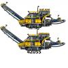
 My latest release, a log trailer with three axles of which the last one is liftable. It comes in two color schemes to match both "US Truck T1 MkII" and "US Truck T2 MkII". Model "Trailer Tr3 MkII” is build with LEGO® in scale 1:17,5 and motorized using LEGO® Power Functions. It is not build after a specific brand or type of trailer. This build represents a three axle log trailer with liftable third axle. The trailer features: solid axle suspension on all axles, one set of lights, kingpin, remotely controlled landing gear and parking break, remotely controlled liftable third axle that simultaneously extends or retracts the rear impact guard and this model has many details. This newly designed and engineered trailer utilizes the same suspension as US Truck T2 MkII which uses LEGO® rubber belts and LEGO® rubber axle connectors. This model is another custom design by Ingmar Spijkhoven AKA 2LegoOrNot2Lego that comes with building instructions and inventory/parts list! You can build it yourself! To do so you can buy the Building Instructions. Early in the building process you will see what it is that you are building. You will be very excited from the moment you start the build of "Trailer Tr3 MkII" till you finish it with a total number of parts of about 1000 pieces. Simultaneously with lifting the third axle the rear impact guard is retracted. So with the third axle down the rear impact guard is fully extended, this to increase safety when hauling loads. Unloaded the total length of the combination is reduced with the third axle lifted and the rear impact guard in. As with most log trailers this model has so called bolsters or bunks. Those are the U shaped frames on top of the trailers chassis. Bolsters are obviously necessary to keep the logs in place. Even though the bolsters on this specific model are fixed they can easily be re-located if wanted. The number of six can also be altered to your own needs. Give this trailer the setup you want it to have. Cheers, Ingmar Spijkhoven
 -
Here is my latest project/MOC. Again it is a re-release and also with instructions. Check mocplans for the instructions and rebrickable for the parts list! Cheers, Ingmar Spijkhoven Introduction: Model US Truck T1 MkII with LEGO® Power Functions® which is a rebuild and revised version of US Truck T1 I finished back in 2009. This model represents the more aerodynamic US truck models like for example the Freightliner Cascadia. Like with all my models this is build in scale 1:17,5. This specific model comes with building instructions available at mocplans.com plus the inventory list available at rebrickable.com. This model features: solid axle suspension on all axles, PF powered driving with power transmitted independently to both rear axles, Ackerman geometry on steering axle, Servo powered steering, fully functional fifth wheel, modeled engine, detailed cabin interior and 3 light units. History of this build To start with a little history on how this model was designed and developed in the first place and how US Truck T1 evolved into US Truck T1 MkII. Back in 2009 I started building US Truck T1 and I really wanted it to have this more aerodynamic looks. From the very beginning of building MOCs I always tried to implement as many realistic features as possible. For example both version I and II of US Truck T1 features full solid axle suspension, Ackerman steering, realistic and working fifth wheel, openable hood, PF drive, PF steering and 3 light units. Design & development process Like with all builds, first a couple of design decisions had to be made: A) First of all I choose not to build this model after a specific brand or type. What I knew is that it had to be a typical US style truck with aerodynamic looks. Inspired by all the amazing US truck brands I just started designing my own truck. Because of my love for work and heavy duty trucks, specifically the Kenworth C500, this will always influence my builds. B) What scale to build in is another obvious quest when building models in general and also for building models using LEGO®. Since most work trucks have a little bigger and heavier wheels my favorite scale for building models became 1:17,5 because this suites me best. Also did I decide to build all my creations in this specific scale. To me it works great when models can be combined. C) I had to figure out what color scheme would work best for model US Truck T1. To start with I do not like building with Black colored items what is the obvious color for the chassis. Never the less this trucks chassis was build in black. With the color of the chassis set I could move on to the colors of the body work. D) Solid Red it became for the body work and I decided not to add any others. Basically because back those days I was very limited in how to add colors to models because of the way I build. Developing as a builder the abilities to add more color increased. I have been told the color of this first edition was a little boring and I agree on this. Why US Truck T1 MkII? In time my building skills develop and so did many solutions I could apply to any build. This specific model could be so much better if I would have build it these days. Because of so many improvements I thought it would be so nice to rebuild this creation. Rebuilding this MOC made me decide to name this updated version US Truck T1 MkII (it is based on US Truck T1, but revised in so many ways). Also did I decide to make building instructions available for it as well! Since 2009 the year in which I finished my first build ever I have been asked for instructions so many times. The process of creating instructions basically forced me to completely revise and rebuild it. Because of this process this new version is way much better and therefore very nice to build. This all together gave birth to US Truck T1 MkII and I am happy with both products: The revised truck itself and the instructions I sell for you to build this model too. Solid axle suspension This truck, US Truck T1 MkII, is build with full solid axle suspension on all three axles, so including the front steered axle. For this suspension to work I did a lot of research, trial and error and engineering. One major problem I noticed was the quite large size of LEGO® Technic Shock Absorber 6.5L. There was no way I could jam six of these into a chassis that is only four studs in between both chassis beams together with everything else that should be in there. Quite rapidly I came up with the idea of using Rubber Belts instead. To achieve this the movement needed to be converted so I came up with a lever constructions. Normally a spring is pushed in and comes back, but a rubber belt is stretched and comes back. Color scheme As I mentioned before I have been told the color of this first edition was a little boring and again I agree on this. Developing as a builder the abilities to add more color increased as did the urge to actually do so. So I started to combine different color combination with this solid Red body work of the model. Always keep in mind to check the availability of parts in a specific color. This forced me to change the color scheme a couple of times. Some key parts in a design may not be available in a specific color or some others might be very hard to get. With the instructions in order to make others build this model as well in mind hard to get parts is an unwanted side effect. Finally I ended up with the addition of both Dark Red and Dark Bluish Gray. These colors really brighten up the Red and give US Truck T1 MkII a classic feel to it. Steering system with Servo A part that I have been looking out to for so many many years is finally available. The LEGO® Power Functions® Servo (part #99498c01) has been release since August 2012. This amazing new electric motor enables the opportunity to create a much more realistic steering system that is also less space consuming. Aligned with the trucks chassis the Servo is sitting inside of the cabin right behind the modeled engine in between both seats. With a 90 degrees conversion the motion of the Servo is transferred to the steering axle. One other improvement to avoid the use of hard to get parts was applied. In order to give the steering axle the Ackerman geometry I initially used Gear Rack 1 x 12 with Holes (part #32132). This has been replaced to make building US Truck T1 MkII with the instructions I sell more attractive to others. Modeled engine inside As mentioned above the Servo requires less space and is sitting inside the drivers cabin. Because of this US Truck T1 MkII is provided with a modeled engine. This truck model is powered by a CAT® CT15 with this very appealing yellow color to it. With the hood opened it really catches the eye. External air cleaners would decrease this model's aerodynamics and with it the full efficiency so these are not mounted. On top of the CAT® CT15 engine there is this internal air cleaner system. The modeled engine is a small object that really improve the realism of this truck model. The engine is very nice to build and to give it those realistic looks a total number of about 120 parts is used. Engine is detailed with for example engine oil dipstick, fan, fan belt, pulleys, hoses, oil filters including by-pass oil filter, turbo, exhaust manifold and so on. Together with much more engine bay details which are added the looks are phenomenal. Openable hood Even though my models are not entirely smooth, so LEGO® studs are allowed to be visible, the hood does not show any studs at all. This really makes the hood elegant. With hinges the hood is openable and not without a reason. What is the use of a modeled engine siting inside if it is invisible. Like with the original version US Truck T1 MkII has an openable hood to give access to both engine bay and engine. With the hood opened one can clearly see the inline 6 cylinder engine with a displacement of 15.21L. With a horsepower range from 450 up to 550 HP and this engine has a torque range from 1550 to 1850 lb-ft. (1202 - 2508 Nm) at 1200 rpm peak torque. Together with the engine a lot more engine bay details are visible. These include break fluid reservoir, windshield washer container, internal air cleaner system and steering shaft. Easy battery box access One key feature that is important when building models with electric features is how to access the battery box as well as the on/off switch located on top of it. In order to make this build achievable for as many builders as possible I sticked with the battery box with 6x AA batteries, LEGO® Power Functions® Battery Box with Orange switch (part #59510c01). Easy to get, used in many sets and a part with a nice price tag to it. The battery box is sitting inside the sleeper. Easy to access by removing a hatch on top of the sleeper. It basically is a part of the roof that can be removed and the battery box is in sight as well as the on/off switch. For those who rather use the LEGO® Power Functions® Rechargeable Battery Box (part #84599) the model can easily be modified. Final improvements One of the noticeable improvement is the windshields window frame. First build used Bar 4L (part #30374) which are basically to small for the job. The new approach looks solid and is therefore more realistic. When TLC released LEGO® Power Functions® IR Speed Remote Control Unit (part #64227) back in 2009 I was really excited about it. First builds also used a XL Motor like this model to drive but with the use of Power Functions Remote Control Unit (part #58122c01) one has to be very careful. Because of the enormous strength of the XL Motor the drive line could be damaged easily. For this very reason the drive line was geared down quite a lot. US Truck T1 MkII has less gear reduction and is therefore quite a bid faster then its predecessor. With the use of the Speed Remote Control Unit both driving and steering became very realistic and therefore the playability of this model is extremely increased! Building instructions To give you an idea of how the instructions for this model will look like here is a preview. Creating these instructions both quick progress on your build and being easy to understand were the main goals. Early in the building process you will see what it is that you are building. You will be very excited from the moment you start the build of T US Truck T1 MkII till you finish it with a total number of parts of about 2250 pieces. To achieve this a lot of floating items are used, with added arrows to show where these items are suppose to be. Together with a lot of so called call outs (the smaller windows within a step that shows the assembling of a smaller sub part of the build) together with multi part steps (not only one part at a time) the build will be in a flow. Check mocplans for the instructions and rebrickable for the parts list!
-
Four years ago, in this galaxy (as opposed to that one far, far, away ), I made a model in LEGO Digital Designer called the MX-2 Rover. Shortly thereafter, I ordered the pieces to build it via LEGO's ill-fated Design byME program. This year, the realization hit me (like an asteroid crashing into an uninhabited planet ) that the steering mechanism was too weakly mounted to the chassis. So, I made several attempts to rebuild the chassis, eventually starting the entire model over from scratch in LDD. Even the shuttle on the back got a revamp. When I felt my design was satisfactory, I took apart the old rover, ordered the additional pieces I needed from Pick A Brick and BrickLink, and built them into... MX-2 Rover - eXtreme eXpedition Edition Now there is suspension on all six wheels and a folding communications dish that is independent from the steering mechanism (on the old model, it was connected to the steering). I also added glow-in-the-dark headlights in the front. Click (or tap, if you're using a touchscreen-enabled device) any picture to see a larger one. Headlights aglow! That gear on the back controls the steering. Here you can see the suspension in action. In addition, the communications dish has been unfolded, rotated, and aimed skyward. The shuttle has been detached from the rover and is "flying" on clear bricks. Browse the Brickshelf gallery, or download the LDD file. This model was designed by Toa Of Justice.
-
Hello everybody, One day my nephew asked if we could make together a car. I started the project last christmas and have actually not made so much progress at the car, but i learned in the meanwhile a lot! I started with zero experience and haven't played a while with lego. Nicjasno was a good person that was very helpfull. The first suspension i made, was very bad according to nicjasno. After watching his video's, i was really ashamed of myself =P. How could i let see such a bad designed suspension to nicjasno! My nephew loves the Ford Mustang GT, and actually i love it to! The scale has in the meantime changed alot. Following nicjasno it was a good idea to build from the wheels. I started with the (http://www.bricklink....asp?P=44772c01) wheels. I followed the idea of sheepo's MacPherson idea. But after some testing i was not convinced enough. When you steer, one side of the car gets lift up because the length of the spring variates. Also an unexpected thing happened. The Powerfunctions XL Motors peforms bad, really bad. (even coupled). After some research i saw you could make your own engine with the lego pneumatics. I started with the one-cylinder from nico71. When i saw it for the first time actually working. The excitement really killed me! I was so excited i wanted to go to the next level. To directly build the biggest, bad-megablocks megablock engines was for me not a good idea. So the next choice was the SYS I3 from nicjasno with all the modifications. After the succesful build. I thought i was ready for the LpePower v8! =O. I have both models kept in my closet and have traded 3 yellow cylinders for 11 transperant blue cylinders. But i'm stil waiting for them. So the next wheelchoice was (http://www.bricklink....asp?P=44772c04), but they were to small to fit the big v8 engine block =P. So we went on to the biggest wheels lego has made: http://www.bricklink....asp?P=44772c03. In the meanwhile i had builded many idea's for the car, but parts broke every time. So we went to the 'heavy duty' category. Nicjasno had tipped me about his HDA. So i had made my own copy of it, but it was really to big! It was such a beautifull designed gearbox. So now, where my question comes from: I started building a rear suspension nicjasno made for his own Ford Mustang GT, but i don't use non-lego wheels with all the extra coming items such as the turntable and the custom adapters. So i had to do it with nicjasno modified wheelhubs (i follow his buildshow). But after many designs that are to big or to wobbly, i ask some advice from the experienced builders on this forum. The thingy that proposes nicjasnos modified wheelhubs and the headpart of the rear suspension (live axle) The wheelhub needs to fit the arms that are coming out, but has any a good idea how? Another photo Nicjasno's models without the cylinders. (I also want to say i appreciate the help of youtuber OOOONeoGamerOOOO with the modifications. I am still learning to do it my own.) Sorry for the bad photo's (original huh?) It is night and i have only a mobile i can acces at the moment. I'm new to this forum so if i do something wrong, i will hear it. Any idea is welcome! Greetings from Jesse, The Netherlands
-
It has been a while since I have been on this forum. To be honest forums are not really my thing, I loose track... Never the less do I like to share my latest creation. It is an older model completely revised. Because I really felt doing so, but also to create instructions. So I did, please have fun reading this. Share you thoughts on it and when you feel like doing so please build it yourself some day!!! Cheers, Ingmar Spijkhoven To start with a little history on how this model was designed and developed in the first place and how US Truck T2 evolved into US Truck T2 MkII. Back in 2008 I started building US Truck T2 after I had finally managed to build a very sufficient and realistic suspension system. From the very beginning of building MOCs I always tried to implement as many realistic features as possible. For example both version I and II of US Truck T2 features full solid axle suspension, Ackerman steering, realistic and working fifth wheel, openable hood, PF drive, PF steering and PF lights. With the chassis still evolving, but good enough to start building the model itself a couple of decisions had to be made: A) First of all I choose not to build a specific brand or type of truck. What I knew is that it had to be a typical US style truck. Because of my love for work trucks brochures available at Kenworth.com became my main inspiration source. B) What scale to build in is another obvious quest when building models in general and also for building LEGO® models. Since most work trucks have a little bigger and heavier wheels my favorite scale for building models became scale of 1:17,5 because this suites me best. C) I had to figure out what color scheme would work best for model US Truck T2. Why exactly I can't recall but the chassis ended up Red and I still love it. With the color of the chassis pointed to Red I could move on to the colors of the body work. D) Searching the Internet for inspiration on this build I noticed that Red and White is a nice color combination. Trying a couple of colors to combine with this evolving color scheme I ended up with Blue. Since not all parts I needed were available in Blue back then I came up with the use of Dark Blue. Because of so many improvements I thought it would be so nice to rebuild this creation. Rebuilding this MOC made me decide to name this updated version US Truck T2 MkII (it is based on US Truck T2, but revised in so many ways). Thinking about the rebuild, not yet started, made me realize that it would also be amazing to make building instructions available for it as well! The process of creating instructions basically forced me to completely revise and rebuild it. So in the looks it is not even changed that much but to get the build going with the instructions as guideline I had to change so many things. Because of this process this new version is way much better and therefore very nice to build. The finished build of US Truck T2 back in March 2009 was basically a result of all the effort I had put in this realistic suspension system. For this suspension to work I did a lot of research, trial and error and engineering. One major problem I noticed was the quite large size of Technic® Shock Absorber 6.5L. There was no way I could jam six of these into a chassis that is only four studs wide together everything else that should be in there. Quite rapidly I came up with the idea of using Rubber Belts instead. So I came up with a lever constructions. Normally a spring is pushed in and comes back, but a rubber belt is stretched and comes back. In the build of US Truck T2 MkII I replaced the hard to get Sand Blue colored parts by Dark Blue ones. Back in 2009 part 30357 Plate Round Corner 3 x 3 wasn't available in either Blue or Dark Blue. These colors I did prefer back then with the build of US Truck T2. This forced me to use this part in the less common color Sand Blue. Even though this was a switch that worked out very well I prefer not to use this color. Mainly because parts in this color are hard to get. So now that these parts are available I had the chance to give US Truck T2 MkII the initial color scheme I came up with for the first build. A part that I have been looking out to for so many many years is finally available. The LEGO® Power Functions® Servo enables the opportunity to create a much more realistic steering system for US Truck T2 MkII. Aligned with the trucks chassis the Servo is sitting inside of the cabin right behind the modeled engine. Since the movement of the Servo needs to be converted 90 degrees a challenge occurred. Luckily we still have this older LEGO® part 4143 Technic Gear 14 Tooth Bevel. Because the Servo requires less space US Truck T2 MkII is equipped with a modeled engine. Because of some parts I needed to build this engine that are only available in Light Bluish Gray this became the engines color. Searching the web for inspiration I noticed Detroit Diesel has some very nice power sources available. Doing some research made me choose to build the DD15. Modeling this engine was very satisfying. A small object to build but to give a realistic look still a lot of parts are used to build it. What is the use of a modeled engine if it is invisible. Like with the early version this revised model has an openable hood. For inspiration I used the Kenworth C500 PDF brochure. One picture shows a truck with a opened hood and shows really nice how a part of the fenders is attached to the cabin. So this part of the fenders stays in place when the bonnet is opened, I really love this concept. One other major improvement is the battery box accessibility as well as the location of the on/off switch. To make this achievable for as many builders as possible I sticked to the battery box with 6x AA batteries. With the original US Truck T2 to replace the batteries the entire roof had to be removed together with the sleepers back side. For the on/off switch I installed a complex mechanism that needed small doors to operate the switch. As complex as it sounds it really was and I was never happy with this solution. The roof of US Truck T2 MkII now has a hatch to access the battery box and the on/off switch. Besides decorative purposes these bars are supposed to support the roof, which they didn't! Thanks to digitalizing my model with BrickSmith I noticed/discovered a much better solution. Besides that it looks less fragile this new window frame really became supportive. When TLC released LEGO® Power Functions® IR Speed Remote Control Unit item number 64227 I was really excited about it. First build also used a XL Motor to drive but with the use of Power Functions Remote Control Unit item #58122c01 one has to be very careful. US Truck T2 MkII has less gear reduction and is therefore quite a bid faster then its predecessor. To give you an idea how the instructions look like here is a preview. Creating these instructions both quick progress on your build as well as each step being easy to understand the same time were very important. Early in the building process you will see what is happening, what it is that you are building. You will be very excited from the moment you start this build till you finish the build of US Truck T2 MkII with a total number of parts of about 1800 pieces. To achieve this a lot of floating items are used, with added arrows to show where these items are suppose to be. Together with a lot of so called call outs (the smaller windows within a step that shows the assembling of a smaller sub part of the build) together with multi part steps the build will be in a flow. Check mocplans for the instructions and rebrickable for the parts list!
-
As mentioned with the release of US Truck MkII instructions for a trailer to go with this truck would be available. I am happy and proud to present them to you. Here is my latest creation: Trailer Tr2 MkII (with instructions). What was true for the revised version of the truck might even be more true for this trailer. Believe me when I say this revised version and the original design are poles apart. In the looks it may not even be changed that much, but don't be fooled by its appearance! This all together brings forth Trailer Tr2 MkII and I am happy with both achievements: The revised trailer itself and the instructions for anyone else to build this trailer. Check mocplans for the instructions and rebrickable for the parts list! Cheers, Ingmar Spijkhoven LEGO® model Trailer Tr2 MkII with LEGO® Power Functions® which is a rebuild and revised version of Trailer 2 I finished back in 2009. Like with all my models this is build in scale 1:17,5, which makes them to be combined!!! This specific model comes with building instructions available at mocplans.com plus the inventory list available at rebrickable.com. This model features: full solid axle suspension, LEGO® Power Functions® remotely controlled landing gear and parking brake and three sets of Power Functions® lights. As with the rebuild of US Truck T2 this writing starts with a little history on how this trailer came in to existence. Because of so many improvements and changes this trailer evolved into Trailer Tr2 MkII and suites absolutely excellent with US Truck T2 MkII. After finishing US Truck T2 back in 2009 I started working on a trailer to go with it. I have always been intrigued by those big American trucks out in the open with all kind of loads on those very easy to use flatbed and drop deck trailers. One other very important concern to me is the playability of the truck and trailer combination so less weight would increase this. From day one of building truck and trailer models I always go for implementing as many realistic features as possible. So this build features full solid axle suspension, LEGO® Power Functions® remotely controlled landing gear and parking brake and finally three sets of PF lights. After finishing the build of the semi-truck or tractor the build of the semi-trailer that goes with it could be launched. Like I do with all builds, first a couple of design decisions had to be made: A) Like with US Truck T2 (and MkII) I choose not to build this trailer after a specific brand or type. What I knew is that it had to be a typical US style trailer. Because of the way I was building back those days I had to give this trailer a drop in the deck. B) Since the scale was set because of the build of US Truck T2 the scale was not an issue. What was an issue is what wheels to use. Even though most trailers used in the Netherlands (Europe) have so called super singles, I prefer to use the same tires as with the truck itself. C) Setting these parameters was a nice start, but more quests had to be conquered. For example what color scheme would work best for this model especially because it had to fit US Truck T2's color scheme. The color of the frame would undoubtedly be Red. Bringing back the Blue would be obvious too. D) One detail that really caught my eye is the alternating Red and White retroreflective strips. Its role is evident and it really breaks the color and the looks of the trailer in a very positive way. E) The final call would be what to use as deck, the floor itself. Most straightforward would be the use of plates in any suitable size. I ended up using modified plates 8 x 8 with grille and hole in center. Describing US Truck T2 MkII did unfold why it was rebuild, allow me to do the same for this trailer rebuild: Since the build of the original version of this trailer my building skills develop and so did many solutions used. Likewise the truck this trailer model could be so much better if I would have build it these days. So I did! Rebuilding this MOC made me decide to name this updated version Trailer Tr2 MkII (it is based on Trailer T2, but revised in so many ways). The process of creating instructions for this trailer as well essentially forced me to rebuild it in total. Not just implementing some improvements. No, there is not much left of the original design. Besides all this the perspective has changed totally because I wanted to create instructions for this build too. So in the looks it may not even be changed that much, but believe me when I say this revised version and the original design are poles apart. My first attempt back in 2009 was to build a flatbed, so a trailer with a one level deck without a drop in it. Because of a lot of decisions I made while building the truck itself with its frame, suspension and fifth wheel, the fifth wheel ended up quite high. To give the flatbed good looks too, it should not be to high on its wheels. It would have been if I would have build it with a leveled deck. So I had to change my mind from building a flatbed to this drop deck. All of this mainly because of limitations I experienced back in 2008/2009 because of my lack of knowledge. I had to learn how to build with LEGO® all over again because of so many great new parts. Even though I am able to build a flatbed these days I sticked with the original drop deck. Since there is quite a lot of it I wanted the floor of the deck to be nice to look at. Functionality is important to me simultaneously as you might know right now, so that counts too. The overall width of the trailer is 18 studs, minus two tiles one on both sides leaves me 16 studs for the floor itself. Divid this by two makes eight studs on each side which gave me a range of opportunities. Quickly it was narrowed down to only two: The most obvious would have been to use plates with a length of 8 and a width of any needed size. Not bad to start with, but not really appealing to me so I continued the search. I ended up with the use of modified plates 8 x 8 "with grille and hole in center". These are available in very nice colors, it has great looks, light in weight and not that expensive. These plates suites the job just perfect, the studs make them what I call "sticky" this to prevent the load from sliding and it could further more be used to attach loads. The trailer's total length and both main and upper deck had to be adjusted to the use of these 8 x 8 plates. Still can't figure why, let me tell you: For the truck I came up with a very nice and realistic functional suspension system. Which I still use in all current projects and I will use in future ones. For some reason I had to use a rather simple suspension system for the trailer. Not that it wasn't sufficient, no it was, but not realistic for this type of trailer. The system itself is not as impressive as how it is referred to: longitudinal pendular axles! In the real world, I mean in the situation it is not a model, this type of suspension would cause a lot of damage. Damage to both trailer and load this because not enough stress is absorbed going over bumps or other obstacles. This rebuild trailer utilizes the same suspension as US Truck T2 MkII it uses LEGO® rubber belts and LEGO® rubber axle connectors. It occurred to me that it would be amazing to make this trailer what I call stand alone. With this I mean that it has a power source of its own. This results into the need of giving it a battery box. Please realize back in 2009 the much smaller battery box that holds 6 AAA batteries was not available. Both beams of the trailer's frame consist of two rows of Technic Bricks stacked with two layers of plates. The main reason to build it this strong was to avoid the trailer to bend under its own weight or load. Because of this approach it was very easy to hide all mechanical stuff and LEGO® Power Functions® in between both beams. Hiding the Battery Box on the other hand seemed almost impossible. So here is what I did: I knew that the part of the trailer from the kingpin to where the wheels are attached to needs to be sturdy, it transports stress caused by the weight of the trailer itself and its load to both king pin and rear axles. The tail part of the trailer could be weaker so I decided to lower the beams at this part. This allowed me to hide the Battery Box and by accident because of its location it could easily hold the rear impact guard. The super singles I referred to are a little larger which would force me to use the wheels as in the Black Cat LEGO® set 5571. These I don't have before all else and I don't want to invest in as well because of the excessive price. Further more I really love the impressiveness of how a semi-truck and semi-trailer combination might be referred to in the United States: An eighteen-wheeler. So four super singles is not an option at all, four dualies had to be mounted! Some following trailers I build after I finished the first version of this trailer in 2009 had smaller wheels mounted. The largest advantage of the use of these smaller wheels is that it reduces the trailer's total weight and frictions. All of this makes it easier to be towed by the tractor and therefore the playability is expanded. As suggested before the alternating Red and White retroreflective strips had to be on my model as well, but without the use of stickers or decals. It just had to be replicated by adding Red and White 1 x 2 plates, but without compromising the trailer's strength. In between every set of Red and White plates a Blue plate 1 x 2 "with handle on side" is located. Real live drop deck trailers are usually equipped with fixed or sliding winches to secure loads. These are used to tie down the load so that it won't move during transport. So there the Blue plate 1 x 2 "with handle on side" became very handy. These are used to tie down the load with the use of LEGO® Chains 5L or 21L or any kind of rubber band. In my judgement a model comes to live by adding details. The more the better, but don't over do this, it will finally work against it. Finally I installed running lights which are on both sides of this trailer. The purpose of course is to increase the trailer's visibility and its looks. The landing gear it self was not that hard to came up with and I started with a manual operated version. It didn't take that much to decide to make it remote controlled. The beams on the trailer do have this space in between of four studs, so hiding the M motor and the IR Receiver are not that hard. Even though the IR Receiver does have two connectors I forced my self to combine both parking break and landing gear. The first version of this trailer had a landing gear that swings up and down. Nice concept, but not flexible when it comes to connecting to trucks with different fifth wheel heights. The trailers front end can be raised or lowered to make it connect to the fifth wheel. Developing the truck's fifth wheel I used a 3L axle with stud as kingpin. The kingpin does not only keep the trailer attached to the truck horizontally, but vertically as well. This means going over a bump should not make the driver loosing the trailer. From the very beginning of building truck and trailer models I planned on being able to combine any truck and trailer I build. With my first approach of the landing gear as described in this topic it was harder. It had to be achieved by making sure that all trailers king pin, landing gear and suspension are all on the same height. As well as making sure the fifth wheel is at the same height. Now the trailer can just be aligned with the truck easily. To give you an idea of how the instructions for this model will look like here is a preview. Creating these instructions both quick progress on your build and being easy to understand were the main goals. Early in the building process you will see what it is that you are building. You will be very excited from the moment you start the build of Trailer Tr2 MkII till you finish it with a total number of parts of about 1100 pieces. To achieve this a lot of floating items are used, with added arrows to show where these items are suppose to be. Together with a lot of so called call outs (the smaller windows within a step that shows the assembling of a smaller sub part of the build) together with multi part steps (not only one part at a time) the build will be in a flow. Check mocplans for the instructions and rebrickable for the parts list!
-
[Edit, 16 February 2013] Another version: Impala Lowrider (the yellow one), see this post. [Edit, 03 February 2013] Picture of the finished MOC, see this post, too: [/Edit] Hi all, another huge American car, still a WIP though. But it might be interesting to see how this will turn out. Don't care about the inappropriate fig, it's just a test driver. The car will be given to a more glamourous fig for sure ... As you might know my idea is that a Lego car should fit 2 figs side by side, so I prefer the 7w building style (although you can do that with a 6w car, too, if it has the thin doors). The car has nearly the same frame as the Cadillac Fleetwood (see http://www.eurobrick...showtopic=78281), but due to the smaller wheels it is possible to have suspension now. There's enough room within the frame for the wheels to move up and down (at the front more than at the back, to be honest). Furthermore the bracket-and-tile building style allows to set down the windscreen to get a nicer silhouette (same with the Caddy). At least in the 6 and 7-wide department there's often a problem to find the proper windscreen. You may use slopes instead, but then the figs can't see where they are going ... Here they can look out properly. Rims are custom chrome, of course. I try to avoid it where I can (the Caddy doesn't have any), but here it's important. C&C welcome as usual, more to come ... Thanks for looking.
-
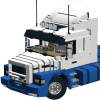 Hey all, My latest MOC is modeled off of a 10x6 Foden S108 crane truck tractor unit run by Mackenzie Transport of Auckland. There are some differences between the real truck and my MOC such as their trucks are white but mine was made in red due to parts constraints and the other difference being that the original Palfinger truck mounted crane on the truck has a five-stage extension on it but my version only has two-stage extension because that was the most I could have before the crane arm became too large and out of proportion. Photos of the original truck can be found here: https://www.flickr.c...ith/6161598123/ MOC's Features: HOG steering Live axle suspension on the rear axles Pneumatically controlled pendular suspension on the front axles Stabilizers Locking turntable Tilting cab with straight six piston engine under the cab Full interior of cab with suspended seats Motorized truck mounted crane with two-stage extension Custom stickers LED running lights The combination with everything expanded This photo is one of my favourites and shows the custom stickers of badging and the original number plate from the truck The truck on its own Everyone's favourite photo, the under shot This photo shows the controls for the crane (the PF switches) along with the switch and pump for the front air suspension The engine without the cab attached The interior The mechanism for seat suspension LED running lights Now for the trailer, a three axle extending trombone trailer. It has full independent suspension, landing gear and of course an extending deck. The trailer extends 29 studs, bringing it to a total deck length of 122 studs/97.6CM. Trailer when extended with lattice boom load Trailer when retracted Trailer suspension system Underside when extended Underside when retracted Another photo of the combination Statistics: Total length with trailer extended: 173 studs/138CM Length of truck: 77 studs/61.6CM Width: 19 studs/15.2CM Height: Truck weight: 2.4KG Trailer weight: 0.8KG Load weight: 0.2KG Pieces count: 4000 +/- Time to build: 60+ hours This is the first time I have used a white background instead of no background and I am very pleased with the results and will definitely do it again. As always more photos can be found on my Bricksafe and for the first time, a video can be found on my YouTube channel! I hope you enjoy my MOC as much as I do Bricksafe: http://bricksafe.com...e/completed-moc YouTube: https://www.youtube....876u7IUZPRGhwrQ
 -
Hey all, I am currently in the middle of doing a complete overhaul of the chassis on my WIP (http://www.eurobricks.com/forum/index.php?showtopic=109478) and I am considering adding full suspension to the model along with making it manual instead of RC. The only problem is that I can't find any good suspension designs for three driven axles with dual wheels in the 1:17 (19 studs wide) scale. I have searched all through the axle collection thread and various other locations and come up with nothing, if anyone can give me a good design or point me in the right direction I would appreciate it. This suspension needs to be compact and without many uncommon parts, with the ability to have the three axles still close to each other due to the fact that it is a tractor unit so it can't be too long. If I don't see a good suspension system and I can't come up with one on my own then I will have to scrap the idea of suspension completely, thanks in advance to anyone who can find a good design.
-
In the last couple of weeks I have, amongst other projects, been working on the rerelease of Trailer Tr1. Here it is this latest project: Model "Trailer Tr1 MkII type T1" is build with LEGO® in scale 1:17,5 and motorized using LEGO® Power Functions. It is not build after a specific brand or type of trailer. This build represents a two axle reefer (refrigerated) trailer with tandem axle slider. The trailer features: solid axle suspension on all axles, three sets of lights, a kingpin, remotely controlled landing gear and parking break, remotely controlled tandem axle slider, and many details. Scale: 1:17,5 Length: 826 mm Weight: 2,78 kg Parts: 1730 It’s color scheme matches that of „Truck T1 MkII” extremely well and so does its aerodynamic looks. The trailer’s weight is reduced by a light weight constructions of both the walls and roof and also by reducing it’s frame. The „container” is strong enough by itself so the frame is only used to attach necessities. These include the tandem axle slider, Power Functions and landing gear. Within a couple of weeks two more editions of this very same trailer will be available. First will be type T2 that fits the color scheme of „Truck T2 MkII” just perfect. The third edition, type Tx will have standard "factory" colors to fit any other truck model available or is to be combined with your own truck design. What is particularly new to this model is the avoidance of the hard to get Black Technic Steering Arm Small (BrickLink ID 6571). The newly designed rear axle now uses another part instead which will be available for many years! To adjust the weight on different axle groups the trailer’s tandem axle group can slide along the trailer. The tandem axle group can be moved forwards and backwards to put the axles where the weight is best distributed. With this the distance between the kingpin and the axle group can be altered. This is referred to as the trailer wheelbase. The longer the trailer wheelbase, the less maneuverable the truck-trailer combination. This model is another custom design that comes with building instructions and inventory/parts list! Early in the building process you will see what it is that you are building. You will be very excited from the moment you start the build of "Trailer Tr1 MkII" till you finish it with about 230 different parts totaling 1730 pieces. Cheers, Ingmar Spijkhoven
-
Hey all, I have been working on an MAN SL202 in the Redbus NZ paint scheme: This model has full suspension including an auto-kneeling function where when the front door is opened the front left air suspension is lowered. I have built most of the chassis and the front and rear suspension, but as you will see the front suspension needs a complete overhaul due to steering problems. Time to stop rambling on and give you some images Air hoses are for the kneeling. Rear view. Front view of front suspension, not the left side wheel is over-rotating when steering and causes the wheel to lock at a right angle to the chassis and stopping forward movement. When it is able to drive the steering is at a bad angle when straight and this causes a large amount of resistance. When the steering is turned the geometry is way off and causes major sledging and resistance. The front axle when kneeling. The pump and RC switch for the suspension lowering and raising. Rear suspension design. Rear suspension's range of movement. Chassis view. So as you can see the project is coming along nicely but the front axle suspension needs a complete overhaul so any designs that work well would be greatly appreciated These photos and more can be found in a bigger size on my Bricksafe: http://bricksafe.com/pages/Kiwi_Builder/Technic.
-
I have been releasing a couple of rebuild in the last couple of months. This has been very satisfying also because of the building instructions I released with them. So many enthusiastic people all around the glove are building my MOCs. Never the less, here is a completely new build: Model "Trailer Tr10" is build with LEGO® in scale 1:17,5 and motorized using LEGO® Power Functions. It is not build after a specific brand or type of trailer. This build represents the well known typical US style spread or split axle flatbed trailer. Another custom design that comes with building instructions and inventory/parts list! Never did I hide my preference for flatbed and log trailers. Basically because this adds the most playability to a build. Once I build this refer and even though it was much fun building, there was no fun running around with it. The weight of this model exceeds the limits of what my semi-trucks are designed to haul. So that I why I build another flatbed, this time without a drop in its deck. Again does this build feature full solid axle suspension on both axles, three sets of lights, kingpin, remotely controlled landing gear and parking break and many details, but it also features toolboxes and a remotely controlled liftable rear axle. Even though it is not very common for this type of trailer to have a liftable rear axle I implemented it anyways. Mainly because of two reasons: A) One channel of the PF IR Receiver is used to operate the landing gear which engage/disengage the parking brake simultaneously. One channel was left to be used. Obviously the second one is used to raise and lower the liftable rear axle. B) The more tires means more rubber equals more friction. To reduce the drawback of it when it comes to playability the most rear axle is liftable. What basically happens is this mechanism forces the suspension to bottom out. Where normally weight would engage the suspension to act now there is this lever that does the work. For this reason this axle is sprung soft, but the the first axle is sprung hard. With the second axle lifted the first axles has to be stiff enough to bare the trailers empty weight. The axle setup of a spread axle trailer is not just randomly picked. It really has a purpose and it all is related to weight. Commonly this axle configuration is mostly found on flatbeds, car haulers and refrigerated trailers. As described this is a typical US style trailer. Cheers, Ingmar Spijkhoven
-
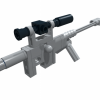 I present my latest MOC, a 6x4 Dump Truck: Click pictures for highres, or visit the BrickSafe folder if you want to It is based off of the chassis I made for my 8x4 Recovery Truck last year, but obviously has lost an axle, and been adopted for remote control with Power Functions. It features: -Drive with two XL-motors -Steering with Servo-motor -Independent suspension on front axle -Live axle suspension on rear axles -Dumpable bed with one M-motor and two LAs -Openable cabin -Openable doors -V6 engine driven from both rear axles, via a lockavle central differential -PF LEDs up front -PF LED reversing lights I found a sloution to steer the rear axle, using a turntable and a linkage to the servo motor, combined with pendular suspension, but it had too much slack, and wobbled all over the place, so I ditched it. I also made a mechanism to lift and lock the rearmost axle, but that to turned out less than satisfactory, so I ditched that as well Pictures! There you can see the red lever above the XL-motor, that engages the central diff The bed is quite spacious I was unsure if the M-motor would be sufficient to tip the bed, but it turned out very well, and it has no problem, even with some load! Close up of the tipping LAs. The driving rinf you can see above the rearmost axle is from the locking mechanism I tried to make, that didn't work. I then forgot to take it out Here the cabin is tilted forward. The battery box is held in a solid structure behind the cabin, as you can see. The servo for steering is placed vertically just below the battery box. Close-up of the V6 engine, including "twin turbochargers" The side panels taken off the battery box compartment, shows the wiring and placement of the servo At the front of the bed, we have a spare wheel, and some tools ...for when you need to change a tyre (obviously) The rear axles with left wheels removed for better view. You can also see where the tipping LAs are attached And of course, the under belly shot An LDD representation of the drive line. Green is where the power from the two XLs come from, purple is the axle to the engine, cyan and orange are axles 2 and 3 respectively. All in all I am pretty pleased with the result, as I've been wanting to build this for a long time! Hope to make a video of it in the not too distant future! I will also perfect the LDD model, make it available for those who want it, and post it on rebrickable. I might even make instructions for it, if I fin the time, and can get LDraw to work again