
(1).png.a1fbc2cb0cea4cdd8143bb892ea370eb.png)
glowytheglowbug
-
Posts
166 -
Joined
-
Last visited
Content Type
Profiles
Forums
Gallery
Everything posted by glowytheglowbug
-
(1).thumb.png.b4d6c907fe73903aec1adfd3cd481a19.png) just curious, what reciever and controller did you use to radio control it?
just curious, what reciever and controller did you use to radio control it? -
Woah thanks for your help, nice to see that the cosin rule i learnt in maths is useful here, with my design as there is no value, g , can i still use this formula? Just changing the g to 0 and setting up my variables for c and a would it work? Also have a nice trip in mexico (if its a holiday) thanks for your help! Theres not much rush to this project anyways.
-
Yep! Tried it out with some buttons, works well now to figure out the inverse kinematics for the legs, do you happen to have a diagram or link I can refer to?
-
can you attach buttons to the nano shield? don't see a way to do so
-
i mean it reminds me that i suck at soldering by the amount of tape on the connections also the color of the wires is fine, ill figure the code out now thanks for your help!
-
is that what its supposed to do by changing the polarity of the pins
-
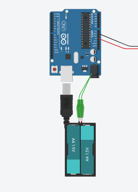
basically the red from my battery goes to the black on the plug, and the black on the plug goes to the red on the battery :D
-
in the connection between my battery and the plug I just swapped it XD
-
there are 2 holes with slots instead of 2 tiny holes as you can see in my picture do you happen to have a video or more pictures of the one you have? ah it works now, has lights and servos move! thanks
-
the leds dont light up, they only light up when the USB on the arduino is plugged in
-
my arduino nano has just arrived btw, the hub seems to not power the servos and I just hear a clicking noise https://www.aliexpress.com/item/4000579100527.html?spm=a2g0o.order_detail.order_detail_item.7.4063f19c462En7 got this arduino btw
-
Ah alright, my 1.4:1 gearing just screws the angle up once it rotates over 360 but it shouldn't happen anyways, thanks! it seems to happen only when I overdraw too much current or when the code crashes
-
Also with my geekservo motors, they don't seem to have a hard stop when they rotate past 360 so technically are they able to continously rotate?
-
Is there a torque reading for the dc motors? Or rpm
-
Also i found some interesting motors and servos 13kg?https://www.aliexpress.us/item/3256805735585376.html https://www.aliexpress.com/item/1005006285236552.html?spm=a2g0o.store_pc_groupList.8148356.15.65aa135c9OnPVH
-
oh thanks, welp starting the collection of useless circuits lol, I'm planning to connect a receiver to the Arduino and use a radio controller (made for a plane) for it by plugging the PWM inputs into the Arduino, would that work for remote controlling?
-
Do you think the pico shield can be modified like the nano shield to make the voltage higher? eg soldering new regulators or capacitors (I don't know) and also increasing the output current to =<800 ma
-
china problems i guess XD my items arrived in about 1-2 weeks and for some reason these take a month more
-
arriving next year on the 23d of jan the arduino shield has 1.5A but the pico shield has only Output current: ≦500mA so im not sure if I can use it to power stuff if I get tired of waiting I can go and buy an arduino manually yes, that's what the shield is for it has a separate plug to power the shield and the servos
-
apparently the output voltage for the pico is 3.3v/5v, do you think I need to do some kind of modification to power geekservos? https://www.keyestudio.com/products/keyestudio-raspberry-pi-pico-io-shield-development-board-for-raspberry-pi (also my arduino nano is taking forever to deliver and will probably arrive next year, so I'm stuck with the raspberry pi for a while) also the raspberry version has these specs Power supply: 5V Output current: ≦500mA DC input voltage: 6.5-12V Output voltage: DC3.3V5V Recommended ambient temperature: -10°C ~ 50°C Size:45.339MM *83.617MM Spacing of pin headers: 2.54mm and since the servos draw 800mA at max is it still ok?
-
Allright, ive just talked to some people, seems like the circuit is wayyy too complicated to do (There's no board that does all of that But you can get a TP5100 2 cell series charger breakout board And a latching switch breakout board to turn it on and off) I have received both a https://www.keyestudio.com/products/keyestudio-raspberry-pi-pico-io-shield-development-board-for-raspberry-pi and a https://www.keyestudio.com/products/keyestudio-nano-shield-board-w-power-switch-for-arduino-nano do you think I can use the raspberry pi pico shield? and what do I need to do to power geekservo motors as the voltage is low?
-
ooh i was just thinking if there's some circuit like this but for 2 cells
-
I think my diagram is a bit hard to read, basically i want to use my two 18650s without having to take them out and in of the battery holder and being able to charge them in the battery holder or connect them to the DC port of the Arduino, the usb port will be connected to the raspberry pi. The reason why i got 18650s is so that they seem to be pretty common and in case one or two die i can easily replace them, when i was searching for batteries, it seems like lion batteries are safer? compared to lipos. I dont need to charge and discharge the batteries simultaneously. also in my robot dog each leg can carry about 1kg and the frame itself is about 400 grams so i have a bit to play around.
-
I just bought four 18650 cells, two will be used in the project to power the arduino and servos, they have 3.7v and 3200mAh each, I also bought a battery holder to contain two cells in series and a raspberry pi (along with yet another arduino), I will be testing out controlling the full robot dog with one arduino first while I wait for my nano and shield to arrive. Is there a circuit to allow me to charge and drain the two 18650 cells while they're in the battery holder eg something like this circuit but the AA's are 18650s and there's a charge/discharge circuit in between the batteries and the arduino (the batteries will be connected to the breadboard too)
-
As in the ball bearings eg wheels or gbc balls?