
Hod Carrier
-
Posts
1,007 -
Joined
-
Last visited
Content Type
Profiles
Forums
Gallery
Everything posted by Hod Carrier
-
[OcTRAINber MOC] LMS Articulated Railcar (1938)
Hod Carrier replied to Hod Carrier's topic in LEGO Train Tech
Thank you, gentlemen. This is the aspect of the design that I feel proudest of, and the one that I think has the widest possible applications by other builders. I suspect that I bought the self-same Star Wars droid set myself and am aware that not all LEGO rubber bands are made equal. The glossy ones are of a different material which makes them less prone to perishing. Sadly I didn't have any short enough for this application, but they are on my list of future upgrades. -
[OcTRAINber MOC] LMS Articulated Railcar (1938)
Hod Carrier replied to Hod Carrier's topic in LEGO Train Tech
This is the point where I have to come clean and make a small admission. Prior to starting my OcTRAINber entry I had already spent several months working on another articulated train which is now an advanced work-in-progress. Therefore, a lot of the engineering decisions that I have made for that design can simply be copied across to this one giving me time and capacity to devote to other aspects of the design. Admittedly this other project has not been built yet so the LMS Railcar would act as a prototype to test these ideas. Therefore, what follows is something that I've been sitting on quietly for several months rather than the fruit of the past few weeks. I had been applying my mind to the question of whether or not it might be possible to come up with a genuine LEGO solution for close coupling. To that end, I spent some time tinkering with some Technic elements to see what might be possible, during which I came up with the following arrangement of parts. As you can see, this arrangement permits a sort of floating pivot point along what is almost a straight line. The advantage of this is that it would permit two vehicles to be close coupled on straights but gives sufficient clearance for curves and movement of the vehicles relative to each other. The original idea had been that this would be used for bogie vehicles. The mechanism would be mounted within the body of the vehicle with a straight bar coupler to join the vehicles together rather than a magnet as normal. Because each vehicle would centre correctly due to the bogies making reference to the track, this should not need anything additional for the geometry to work. At present, I have not had any time to build or test this idea. The problem with articulated vehicles is that this would not work correctly since it relies on each car making it's own reference with the track. Because articulated vehicles share a single bogie, the only way to achieve this would be to have two pivot points, one per car, as quite a few builders decide to do. The downside of this is that it doesn't result in accurate movement of the train through curves and points/switches, which is something that I wanted to avoid. The majority of articulated vehicles use a single shared pivot point over the bogie which means that the cars can articulate independently of bogie and the bogie rotate independently of the cars. So how am I going to make the cars centre when there is nothing to apply the relevant force? Simple. I use a rubber band which pulls the end of the mechanism back towards the chassis centreline. Two cars coupled. The bogie is pivoting around a 5L Technic beam, which is conveniently hard to see because it's black, which forms the bar coupling between the cars. You can see the offset in the mechanism due to the articulation between the cars. Articulation and bogie rotation work independently as intended. A quick spin around a test track shows that it's working just as I hoped it would, with everything running nice and smooth. It even copes well with LEGO's horrible R40 curves. I'm just hoping that adding weight to the cars as they are built up does not negatively impact on this. On the downside, the use of rubber bands does now mean that this is a mechanism that will require servicing from time to time as the bands perish and need replacement. The other aspect of this which I think is a bit of a shame is that this is the sort of thing that's quite clever but, because it works well, is likely to go almost totally unnoticed when the railcar is finished. -
[OcTRAINber MOC] LMS Articulated Railcar (1938)
Hod Carrier replied to Hod Carrier's topic in LEGO Train Tech
I hope I haven't over-promised and end up under-delivering. Watch this space for developments. Thank you. I'm glad I could come up with something that works, but it is a fairly bulky solution that is causing some new headaches in other areas, but I'll find a way to work around those. I have. The Disused Stations page is probably the best overall summary of the development of the railcar, and a bit of a departure for a site that normally focuses on stations, infrastructure and services. Of course, as this specific page relates to the history of Cambridge station and it's railway connections, it focuses on the period when the railcar operated within the area and shows photos of it there rather than elsewhere. (As an aside, Disused Stations is a brilliant website for browsing if you're at all interested in British Railway history as it documents not only closed stations and lines, but it captures former methods of working and services too. It's worth an evening just for the photos alone.) The entry on Wikipedia takes the information largely from the Railways article of December 1949 that I linked to in my previous post. As far as I can ascertain, this is the only source of information relating to the railcar in it's later guise as a maintenance vehicle. Luckily for me, the British Library in London hold copies of both Railways and The Engineer, as well as a few other promising titles, that may yield some more detailed information, and I will be heading up there in a couple of days to try and see them. You may well be right about the use of images from The Engineer article, but without seeing it for myself I wouldn't know for sure. I'm hoping that maybe there will be some other visuals (diagrams, drawings, etc) or at least a reasonable description that might help with the build, but I'd be happy if I only find out that I've already seen all there is to see and there's nothing more. Either way, I can get on with the design by following the information I discover or by going my own way and making something up that at least looks reasonably convincing. -
1/32 scale Volvo PV 831 Railroad Inspection Car
Hod Carrier replied to Sven J's topic in LEGO Train Tech
Oh, I say!! Now that is something rather special. No doubt the slightly larger scale has helped, but it's still a small build and you've captured the iconic Volvo shape very effectively. Personally I don't mind the slower speed of the Circuit Cubes motor, but man it is loud!! -
[OcTRAINber 2022 - Moc] - FS Vnx806.200 in 1:87 scale
Hod Carrier replied to Paperinik77pk's topic in LEGO Train Tech
Well it definitely works!! I like what you've done with your builds. So often 4-wide forces big compromises onto a build, but I think you've done an amazing job to capture your chosen subject, especially when you consider that you're building in a rare and awkward colour. -
[OcTRAINber MOC] LMS Articulated Railcar (1938)
Hod Carrier replied to Hod Carrier's topic in LEGO Train Tech
While I wait for the Bricklink orders to come rolling in, it's perhaps a good time to turn our attention to what happened next for the LMS articulated railcar. When we left the story last, the railcar had been stored out of use following the outbreak of war in 1939. So, what happened next? With the end of hostilities in 1945, the railways were in a poor state and the railway companies not in any position to restart any experimental schemes that had been underway prior to the war. The main priority was rebuilding and re-establishing a peacetime economy. Nationalisation and the creation of British Railways followed soon after in order to deal with the backlog of maintenance and to make good bomb damage to the infrastructure and losses in locomotives and rolling stock. It would seem that the newly nationalised railway had no interest in developing the LMS railcar any further, but it still remained as an asset. It was decided to convert the railcar for use as an overhead line maintenance train on the Manchester South Junction & Altrincham route, which had been electrified before the war. The advantage of using a diesel railcar rather than a steam hauled maintenance train for this purpose should be obvious. There is not much information regarding the conversion of the railcar, and it seems to have attracted little to no attention during this phase of it's existence. The only source material seems to be an article in a 1949 edition of Railways journal, which handily survives online thanks to the LMS Carriage Association who reproduced it in an edition of their online newsletter. This contains a brief description and the only three photos of the maintenance train that I have been able to find. The trouble with this lack of information is that it makes it hard to know how to design and build a model of it. So far, this is what I've come up with. It looks like a totally different train, doesn't it? However, I have retained the body profile of the original as much as possible to show the family lineage. At the moment this is very much v1.0 with a lot that still needs to be addressed. As you can probably tell, I have so far simply designed one car and copied and pasted it across to make a second to give an impression of how the railcar should look. If you compare the renders with the photos in the article, you can see that there's going to be quite a lot I'm going to have to guess, including the colour. I've opted for dark green because that was the colour of passenger railcars (DMUs), but also because the photos show that it had a lined livery rather than being painted a plain colour. What I cannot see is the layout of the equipment below the floor or the layout of windows and doors on the second vehicle. It appears that there is a toilet because there is a window that has been whited-out, but apart from that it's hard to see anything else. One aspect of the design which has already caused some headaches is the roof. Having a working platform on the roof means that there is a safety lip at the edges which I obviously wanted to retain, but I still needed some way of attaching the cheese slopes at the roof edges. The result of the need to use brackets meant that the roof was narrowed by half a plate at each side from 5 studs, already an awkward number, down to 4 and a bit, so I couldn't just lay tiles and call it done. It was going to need a different solution. It took a bit of mental gymnastics but I finally arrived at a solution that I am satisfied with. Underneath it's a riot of brackets holding everything together. Apart from this, the rest of the structure is fairly conventional. Because this version of the railcar did not have the streamlined paneling, the construction of the model is very different from the original version and uses some more conventional techniques. The lack of source information is a real issue for me in designing this version of the railcar. The photographs accompanying the Railways article are of poor quality and a very long way from comprehensive. I only have a single grainy three-quarter image of one side of the railcar and no idea of what the other side looks like. Even pre-war photos of the railcar without it's lower paneling give little idea of the layout and appearance of the underfloor equipment. The only option that I have left to me to try and gain any better impression is to take a trip up to London to visit the British Library to see an original copy of the article and hope that the photos are of better quality than they appear in the LMS Carriage Association reproduction. To complete the story of the LMS articulated railcar, it would seem that the railcar saw little use as a maintenance train and was moved from depot to depot before finally ending up at Longsight in Manchester. Here it fell into a state of dereliction and was finally disposed of in 1967. -
Octrainber 2022: Atg-1 deicing with a jet engine
Hod Carrier replied to XG BC's topic in LEGO Train Tech
LOL!! Ah well, no matter. You've produced two very satisfying models of the loco in it's "before" and "after" phases, including a very detailed jet engine, which is something that I'm sure very few of us "railheads" have ever had to consider. Agreed. Even if you can't do it in time for the deadline due to your other commitments, it would be good to see this built at some point. -
[OcTRAINber MOC] LMS Articulated Railcar (1938)
Hod Carrier replied to Hod Carrier's topic in LEGO Train Tech
I agree, but sometimes it can be difficult to integrate Technic parts with System bricks because it has a slightly different geometry. Thank you. That's very kind of you to say. We have seen Zephyrs and other round fronted trains down the months and years, some using different techniques. I think that what I've done is just a different approach to the same problem. Grazie, Davide. That's very high praise indeed. I'm pleased that you like what I've revealed so far and hope that the finished product meets your anticipation. I have to confess that I've not experienced problems with pinned Technic bricks sagging. The trick that I've employed is, as with all LEGO joints, a generous parts overlap and plenty of friction pins. If anything, I'm more suspicious of stacked plates as I have found that once you get out beyond a certain length the construction takes on a banana shape that means it needs securing at both ends and in the middle too. My experience is that bricks, Technic or otherwise, are far more resistant to this distortion and, because of the rigid sides, less prone to vertical flexing. I appreciate that joining bricks together introduces points of weakness where flex can creep in, which is why I try to design in such a way as to mitigate against this. Looking back at previous builds I have found that a lot of them have exceptionally strong structures. I really do build them like tanks. In this instance, the spine is built up with plates, tiles and interior detailing and will have the various other sub-assemblies attached, either directly or indirectly, which will be stiff in other axes and add to the rigidity of the whole. I am not anticipating too many issues, but overall rigidity is in the back of my mind and I am prepared to perhaps make alterations as the build progresses to address any problems that may arise. I have something that works quite well as "table scraps" but will need to be built and tested before I say anything much more about it. However, if it works as I hope it will, I should be able to run this model on tight curves (perhaps even R40s) even with the car spacing you see in the renders above. -
Fantastic work, Holger. A lot going on in a fairly modest space, but then port areas are often exactly like that. Best of luck in the category.
-
Octrainber 2022: Atg-1 deicing with a jet engine
Hod Carrier replied to XG BC's topic in LEGO Train Tech
Does that mean that you’re also going to build the MiG 17…? -
Octrainber 2022: Atg-1 deicing with a jet engine
Hod Carrier replied to XG BC's topic in LEGO Train Tech
That’s looking really good. Lots of great details and a really good representation of the jet engine. I like it. -
[OcTRAINber MOC] LMS Articulated Railcar (1938)
Hod Carrier replied to Hod Carrier's topic in LEGO Train Tech
I took a couple of days away from this project as it was starting to loom large in my life. Even while I was busy at work I was thinking about how to achieve the next step in the build, and I was even going to bed at night and dreaming of it. As it turns out the break did me good and I was able to come back to the build with a host of ideas to try. At the end of the last update I had arrived at shape for the body that I was happy with and was trying to work out how to join it all together. One of the main issues was that different sections were orientated differently, with studs facing up, down and outwards as well as sections hung from clips at unusual angles. Obviously this was going to be a bit of a problem, especially as I still needed to leave enough room inside the cars for an interior, motors, batteries and so on. It took a few days and a good dose of experimentation to come up with a solution. The solution that I went for was a spine of Technic bricks pinned together from which everything else is hung. The hope is that, with the roof, this will provide the coaches with sufficient stiffness once the body assemblies have been added. I predict that it may be a bit fragile when handled but it should be fine for running on tracks. This car is the one without the motor, so there is enough space for interior detailing. Some of the details have had to be bent to fit around the structure of the car but luckily there was still sufficient space for an almost full complement of seats. Once you've signed-off on the first car it's a quick job to turn out the others. All the difficult decisions have been made and it's simply a case of copying them over. The original train had three coaches articulated on shared bogies. In this form it looks every inch the streamliner. I suppose that now is as good at time as any to share a little history of this train. During the inter-war years most of the major rail companies in Britain were experimenting with diesel railcars. Most of these were single coach trains such as the GWR diesel railcars with the option of adding a trailer coach if the need for more accommodation ever arose. However, in early 1938 the LMS unveiled this streamlined 3 car articulated railcar which was quite unlike anything before being a multi-car multi-engine fully self-contained train. Painted in bright red and cream with a silver roof, the shape put a lot of people in mind of the record-breaking German "Flying Hamburger" diesel train. The train was powered by six 125hp Leyland diesel engines, two per car, each powering one axle each through a hydraulic transmission. Weighing just 74 tons the train was intended to reach 75mph but actually hit 82mph on an early test run. After initial tests the train was allocated to the Oxford to Cambridge route where it ran a limited passenger service before being moved to the London St Pancras to Nottingham route. Early experience showed that the train suffered with overheating due to the lower paneling restricting the airflow to the radiators. Remedies were sought, but in the end the lower panels were simply removed. The outbreak of the Second World War saw the operation of the railways change to address the national need and many modernisation programs were simply shelved. This railcar was no exception. It was withdrawn from service at the outbreak of war and stored for the duration of hostilities. My own interest in this train is down to various reasons. What first drew my attention was simply due to the way it looked. Along with the original AEC railcars built for the GWR it looks outstanding, especially when compared to other railcars of the era. But as my job is to drive this train's modern descendants, it impressed me with it's modern technology. It contains features that are still familiar to me in my work, such as a door interlock circuit that prevents the train being driven away with the doors open as well as stopping them from being opened while the train is on the move, and automatic engine shutdown in the event of low oil or coolant. As a consequence of all these factors I had bookmarked this train in my mind as a possible future build. I like to pick unusual trains that maybe people have not heard of before and to bring them to wider attention, and this was a perfect candidate. Knowing what happened to the train once it re-emerged after the war made it perfect for this year's theme and gave me the push to try and build it. Tune in again soon to find out what happened to the railcar next. -
[OcTRAINber 2022 - Moc] - FS Vnx806.200 in 1:87 scale
Hod Carrier replied to Paperinik77pk's topic in LEGO Train Tech
Ooo!! 4 wide. That’s a fantastic idea. I do like a nice sub-scale build. I look forward to seeing this one come to life. -
[OcTRAINber MOC] LMS Articulated Railcar (1938)
Hod Carrier replied to Hod Carrier's topic in LEGO Train Tech
Thank you for the positive feedback. This design has certainly been giving my poor brain a good work-out. If things continue to go well there might be one or two more techniques to share. I always start my builds digitally but always design with building in bricks in mind. Therefore I always try to make sure to use existing parts in available colours and to ensure that everything fits together as strongly as possible. I fear that this particular build might be a bit fragile for handling but should be OK to run on tracks. … or at least I hope so. -
[OcTRAINber MOC] LMS Articulated Railcar (1938)
Hod Carrier replied to Hod Carrier's topic in LEGO Train Tech
Thank you for the positive feedback. Like Mr Scott, I cannae change the laws of physics but I can do my best to try and deliver. [Sniff] No, I’m not too congested. Oh, you mean the model. Doh!! It’s actually not too bad so far. Im still exploring different options at joining it all up inside but it looks like there might still be enough space for some sort of interior. The cab is pretty solid though, as you’ll have seen. The curved piece could maybe work for the cab roof if it was in LBG, but it’s not in very helpful colours at present. The cab appears to be a more elliptical than round, which is something I may have to revisit, so perhaps it would be less useful. It’s a good new part though. -
[OcTRAINber MOC] LMS Articulated Railcar (1938)
Hod Carrier replied to Hod Carrier's topic in LEGO Train Tech
Heavens!! Thanks so much for the amazing feedback. @XG BC In Britain we have a very small structure gauge which means that rail vehicles end up curvy in order to maximise the space inside. It's a bit of a pain from the modelling perspective, but it does mean that we have some lovely looking trains as a consequence. It's certainly a challenge. @Guyinaplaguemask If you're used to building planes then I guess that these techniques are already very familiar to you. Most train models end up square (mine included) which can limit what you can accurately model, but that's not a problem as long as the train you're basing your model on is also square. I'm afraid that I don't really have enough time to work up instructions for my builds and wouldn't normally share files for something like this, but I'm more than happy to share the techniques used if that helps other builders to work out how the design fits together and maybe to apply them to their own designs. Please do ask if there's anything inside you'd like to see, but please bear in mind that the design is evolving and is still quite a long way from being ready to build. @Vilhelm22 Being a Brit I just had to pick something British. It is an unusual and unique train and I really should get around to filling-in some of it's history. I think that there may be more than one GWR survivor, but then they built railcars in much larger numbers which meant that they had a better chance of staying in use long enough to be preserved. There was only ever one of these LMS articulated railcars and it was very much a prototype. @Toastie @LEGO Train 12 Volts I'm speechless. Thank you for the wonderful feedback, but the high praise is really not deserved. As you observed, I just wanted to make sure that I got the design looking the best that I could and I wasn't satisfied with any of the earlier versions. I really wanted to push myself this year, get out of my comfort zone and try some new techniques, as I'm very aware that a lot of my earlier builds use only very conventional building methods. So far it looks good on a computer screen but the real test will only come when I try and fit it all together using real bricks. It could all still go to south, but at least I tried. -
[OcTRAINber MOC] LMS Articulated Railcar (1938)
Hod Carrier replied to Hod Carrier's topic in LEGO Train Tech
Time for an update, I think. It's funny how words can come back and haunt you. I seem to remember saying that the cab would be the hard part and that once I'd got that sorted the rest of the build would flow naturally. Well it turns out it isn't as easy as I thought. Here's the first effort. I actually quite like it because it looks very retro, but it's actually quite badly wrong. The windows are too large, the shape is too angular and I seem to have given the roof a shallow clerestory. Well that's the roof smoothed off a bit. On the downside it is perhaps a little bit too flat and this design raises the bodyside by an extra plate making it look square. For some types of train this would be fine, but this one is meant to be streamlined. OK, so the windows are now a better size and more in proportion with the prototype. Lets try some curves. Oh dear, I seem to have given myself a whole new problem. Now I can't get the body profile to be consistent. That's no better. OK, so clearly trying to build this thing using conventional techniques isn't working. I need to think harder. Ooo!! Hello lovely. Look at you. This is much more like it. It's got curves which are consistent along the entire length, a smoother transition between the sides and roof, and the roof itself has been redesigned to give it a better shape. Adding a bogie and posing it on some track shows that the proportions look about right and that there's adequate clearance too. I think this might be the shape that gets built. Now I just have to get on with the unsexy task of making sure that all the different sections fit together to create a strong, stable whole. A slice through the body to show how it's been done. Obviously I will need to try this out with real bricks to make sure it works as advertised, but I have designed it to be built for real and the clearances seem to be OK. -
Octrainber 2022: Atg-1 deicing with a jet engine
Hod Carrier replied to XG BC's topic in LEGO Train Tech
That's fair enough. I tend to be a bit slower because I know that I will spend a lot of time fiddling about making sure that I try and get all the details right, so I have to be organised when there's a competition deadline coming. So I'm pushing myself hard with this design to make sure I don't run into any problems later. -
[OcTRAINber MOC] LMS Articulated Railcar (1938)
Hod Carrier replied to Hod Carrier's topic in LEGO Train Tech
There's going to be quite a lot of guessing going on with mine too. I think I know what colour it should be, but I have no idea about some fairly major details. The trouble is that the source material is just a scan of an article published in 1949, a time when magazine articles carried very few photos and those that they did have were frequently very poor quality by modern standards. It also doesn't appear to have been photographed by train enthusiasts at the time as I don't think the railcar got much use and failed to attract much attention at a time when photography was a fairly expensive hobby. I don't imagine many folk at the time would have wasted a film exposure on it during the era when the railways were nationalised and steam traction was in it's final decades. That said, I'm still searching and trying to find whatever information there might still be out there. -
Thanks Richard. Are you posting the entries onto the BTA Facebook page as you did last year or can we find them elsewhere?
-
Octrainber 2022: Atg-1 deicing with a jet engine
Hod Carrier replied to XG BC's topic in LEGO Train Tech
Wow!! That's coming along very nicely. I like how you've got the slope of the bonnet ends. You do know that you have until the end of October to finish? At this rate you'll be finished by the end of next week. -
[OcTRAINber MOC] LMS Articulated Railcar (1938)
Hod Carrier replied to Hod Carrier's topic in LEGO Train Tech
Thank you, @XG BC and @Darkkostas25. That's most kind. Of course. Here's a quick look inside at the mess precision engineering that makes the shape possible. It's a fairly vanilla concoction of plates and clips, but the challenge was arranging them to give this shape. Er, sort of. I have seen a photo online as part of a document so I do have an idea what it looks like and will be coming around to that later once I've got the tricky original shape sorted out. -
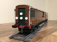
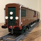
I guess it's time to show my hand and reveal what I shall be building for this year's edition of the OcTRAINber contest. Having been caught out last year I have decided to get an early start. [Hubris] After just playing for laughs last year I have decided that this year I want to be in with a shout of a win, so I'm coming out swinging and I'm gunning for all you other builders. I'm really going to be pushing myself hard to build something worthy of the contest and that will put everything else in the shade. [/Hubris] As this years theme is all about transformations I wanted to try and find a prototype that has undergone a major change. Although quite a lot of railway assets get repurposed quite a lot of it results in only modest changes to their appearances, and that really wasn't satisfying to me. I did make a quick study of the undercroft at St Pancras station in London, but I was concerned that this might turn out to be a bit simplistic. So it was back to the internet for another trawl. I remembered having read about an experimental diesel railcar built by the LMS during the 1930s which underwent a fairly major transformation later in it's life. I had marked this down as a potential future build but had got no further than that with it. Although there were images of the train in it's original form I didn't recall ever seeing any images of it in it's second incarnation. This would be a good option, but only if I could cross a couple of hurdles first. Firstly I had to try and find some photos of the railcar in it's rebuilt form and then I had to satisfy myself that the shape of the original railcar was not going to be beyond my abilities to build. It took a while to tick the first of the boxes, but I managed to track down a reproduction of an article published in 1949 which includes a single grainy black and white image. It reveals very little detail, so I shall try to be faithful to what I can see and exercise judgement about everything else. I shall post this image later to show the extent of the transformation, but for now I shall be concentrating on the railcar's original condition. So with two versions to build it was time to see if I could bend bricks to fit the shape. I decided that the "make or break" area of this train would be the cab. In keeping with 1930s ideas about streamlining, the front of the train is curved with numerous windows inset at angles. If I could crack this then the rest of the build should flow quite naturally. And here it is. I'm actually really pleased with how it's turned out. It took a lot of faffing about adjusting angles and placement of the hinges, but by trial and error I have arrived at a shape that I am happy with. So now it's time to build the rest of the train to go with it.
-
Octrainber 2022: Atg-1 deicing with a jet engine
Hod Carrier replied to XG BC's topic in LEGO Train Tech
I went for Option 2 for the power bogies on my CIE CC1 loco, and it works OK(ish) on R40s. It's actually a technique I first saw used by @dtomsen. Your loco should be fine as it looks like it's got a wheelbase 2 studs less than my loco plus, as you say, it makes detailing easier. -
Octrainber 2022: Atg-1 deicing with a jet engine
Hod Carrier replied to XG BC's topic in LEGO Train Tech
I thought you were going to make the jet-powered Budd railcar.