
npicard
-
Content Count
19 -
Joined
-
Last visited
Posts posted by npicard
-
-
Brilliant! This looks great and seems to work well too.
As for the effect at the beginning of the video, I thought it was convincing. Nice video editing. :) As the cart reached its destination, I noticed a little wobble, but that just makes it look like the train track is a cantilever. There's no hint that it's vertical that I can see.
-
For this (small?) mechanism, I had the following design spec: there should be eight output axles, and they should be powered one at a time, so only one is turning at a given time.
(For those following the larger project, this is the clock, part of a computer processor that provides timing for all the other parts. It's like the conductor of the orchestra.)
Over the course of 8 or so prototypes, I came up with a system which had two pairs of Chiron shifters connected to two driving rings each. The idea was that I'd power the left side and right side alternately. However, I realized that I could just fold the two pairs of shifters into one.
I've never seen four driving rings placed in a square around one Chiron shifter before. I'd be interested to hear if anyone has used this in a build before!
In my final build, power goes into the two blue axles (simultaneously, in the same direction). The outputs are the eight pink gears. Every time the bottom shifter turns 180 degrees, the mechanism switches from powering the North and West output axles to powering the South and East axles. Meanwhile, every quarter turn of the top shifter changes which of the four gears is powered, either on the left or the right, depending on which is powered.
To get all the switching to line up, the bottom shifter should make a quarter turn for every half turn of the top shifter. This way North, South, East, and West each get a turn in the output axles on the left, before power is shifted to the right. After a full cycle, all eight gears are given an equal turn being powered.

Of course, the mechanism needs connective tissue for structure, to provide input power, to turn the shifters, to keep them aligned on 90 degree increments, and to gear down the motor. I used a PU XL motor geared down by 1:64 for the power and 1:1536 for the shifting. Just for completeness, this means each output gear turns 24 times before switching and the whole cycle takes a little less than 5 minutes.


In researching for this build, I was really surprised that I couldn't find any sequential gearboxes that "wrapped back around." As in, 1-2-3-4-1-2-3-4... They all seem to go sequentially up, then back down.
Hopefully it goes without saying that the eight outputs in this mechanism could be connected to different gearing ratios and then unified afterwards. This would create a sequential 8-speed gearbox that wraps around from 8th gear back to 1st gear. As far as I can tell, this is a totally novel mechanism. If I'm wrong and it's been done before, I would really appreciate seeing another approach!
-
3 hours ago, MinusAndy said:As promised, here’s how I’ve used a sliding worm to perform two functions.
Input is via the red axle, the worm climbs along the dark grey gear due to friction added to it using the dark grey 8t gear mounted on a friction pin.
the worm has a shuttle mechanism attached to it which has around 3 studs of linear movement. When it reaches either end of its limit the worm then turns the grey gear and the output from that is used to disengage the power from the input. The limitation on this is that the shuttle mechanism can only move something that requires less effort than is needed to turn the grey gear.Nice! But how is it that the shuttle doesn't get caught on the teeth of the z24 gear? It always seems to be a problem for my builds, so whenever I've needed a shuttle structure, I've resorted to the 1L worm gear. (A poor solution, since it has friction.)
It almost looks like the worm gear and the z24 gear are under-engaged, and the z24 gear and the z8 gear are over-engaged. Is that the case? And is it deliberate? If it's not the case, how did you solve the catching problem?
Thanks for sharing.
-
15 hours ago, MinusAndy said:Wow! That is an incredible project, and a huge build. Do you have any more wip pics?
Next time I access the inside of my Moc I’ll take pics of the sliding worm switch.
Here's a WIP: a functional 3-bit adder. It takes 3 booleans (represented by the red axles rotating either clockwise or counterclockwise, on the far right side in the pic) and outputs a 2-digit binary number representing the sum of those three booleans (near left side).

Unfortunately, you can't see how it works due to it being too densely built. Ultimately, I'll probably end up doing a series of videos explaining the principles behind it.
-
1 hour ago, v01p said:Very cool and elegant! Apologies if this is a dumb question -- what's the reason for the "output needs to be driven" constraint? In practice, would the inputs ever be neutral?
It's actually a very good question. I suspect most people won't care at all.
In my application, a demultiplexer will send power to only one logic gate out of a parallel bank of logic gates, then their outputs will all be joined together, so that the input to the demux has logic applied to it and is then output to one axle. When the logic gates are all joined directly, the one selected by the demux will drive the final output, but will also drive all the other logic gates backwards. Their inputs will be neutral since they were not selected by the demux.
If none of this makes sense, I suppose you'll have to wait for my final design to be revealed! Suffice to say that dozens of these will be driven backwards at one time. Friction is at an absolute premium.
-
Thanks for all the nice messages, everyone. If anyone gets any use from my mechanisms, I'm happy.
Here is what I mentioned a few days ago, and AND gate.
If both green inputs are rotated clockwise (representing "1"), the pink output rotates clockwise as well. But if either (or both) of the green inputs are rotated counterclockwise (representing "0"), then the pink output will rotate counterclockwise.
I have gone through about ten revisions to get it this small, reliable, and low-friction. Unfortunately, it still has high-friction moments when the green inputs are neutral and the pink output is driven (i.e. the mechanism is run in reverse). And it can always be smaller. :)

-
On 10/3/2021 at 7:36 AM, MinusAndy said:These are great. I’ve used something similar to your worm gear clutch ring mechanism to auto disengage the clutch when the worm reaches the end of its travel.
I find components with axle holes but no friction incredibly interesting and useful. I'm always glad to hear of mechanisms using them and I'd love to see yours.
As far as I know, there's only the 2L worm gear, the red z8 gear, and the changeover catch. Does anyone know of any other "loose" axle connections?
QuoteMore importantly. What’s your big project???
I'm making a fully mechanical computer. It's my high-level design is close to final, but there are a lot of details to work out. To illustrate a small piece of it, if you combine my rotational driving ring selector and my two-way-to-one-way, you get a logic gate. The final result should have around 100 logic gates, along with a lot of other "connective tissue." I've been at it for four months and I'm currently estimating it will take me 2-3 years.
-
22 hours ago, MangaNOID said:This is very nice!

with the low friction driving ring you can ‘flex’ out the two middle tabs a little to loosen Or eliminate the friction. Is this the same as what you have posted or does your solution have more too it?
Thank you! That would achieve basically the same result. However, my final build will have dozens of driving rings and I want my techniques to be universally applicable. I am not willing to modify or damage any parts to make it work. Of course, that's just me. To each their own!
-
I am working on a very large-scale project, but I keep coming up with small mechanisms along the way that may be useful to others. I plan on using this thread to collect them.
Of course, I stand on the shoulders of giants, and most of my mechanisms are merely refinements of the work of others. I'll credit where I can.
As I'm new to this forum, I might take this space to briefly introduce myself. I built a lot of Mindstorms as a teenager in the RCX days. Then I had my dark ages from around 2007 until 2019. I decided to get back into it and purchased the 42100 Liebherr 9800. I'm mostly just interested in functional mechanisms.
Two-way to one-way converter
a.k.a. one-direction output

This is is a mechanism that takes rotation in either direction as input (green) and outputs rotation in only one direction, no matter what the input direction was. In this configuration, the red axle only outputs counter-clockwise rotation. Swap red and grey for clockwise output.
Inspiration came from this page: https://www.instructables.com/member/Jorbs3210/
I have seen and tested many of these mechanisms, but none that I found met my three biggest constraints:
- works in any orientation (doesn't rely on gravity)
- very low-friction (so, no rubber bands, no friction pins for idler gears, and not too many gears in total)
- if the input is in neutral and the output is being driven, it won't bind up
This final constraint is the downfall of most other solutions. If you rotate the output axle, gears will bind together and the whole thing will lock up. In my solution, the white 3L liftarm touches the studs of the grey 1x2 plate during operation. This prevents the gears from over-engaging, meaning they can't bind no matter which axle is driven. This has a nice bonus effect of keeping friction low.
Rotational driving ring selector

This mechanism takes constant rotation as input (green) and, based on whether it is clockwise or counter-clockwise, selects between two states of a driving ring. The benefit of this system is if the input is connected to a powertrain that is also doing other things, so it can't be "turned off" when the correct gear is chosen.
When you turn the input clockwise, the blue worm gear travels forward and eventually hits the light grey stop. Then it begins to turn the z8 gear, which turns the white 2L liftarm, which flips the red changeover catch.
This is based off of Sariel's pneumatic autovalve: http://sariel.pl/2008/12/pneumatic-autovalve/
@Keegan Pilling suggested Sariel's solution. I just worked out the details.
Low-friction driving ring axle

In the previous mechanism, I found that the white driving ring axle (that keeps it engaged with clutch gears with a "click") is too high-friction. The input needs to be fairly high torque. Unfortunately, the zero-friction 3L axle connector doesn't keep the driving ring in place at all. I was seeking a solution that was a balance between the two, providing just enough friction to keep the driving ring engaged with the clutch gear, and no more.
@2GodBDGlory provided the idea of using a 2L axle connector with a 3L 3.18 bar. I found it paired well with a 3/4 pin.
I hope these are helpful for someone! I'll post more as they occur to me.
-
14 hours ago, 2GodBDGlory said:Here's a slightly stronger and more compact version of my solution. Unfortunately it doesn't solve your main problem, but I think it's better in other respects.
Update: this solution doesn't work as-is for a surprising reason. The 3L bar is exactly 3L. The 3673 Frictionless Pin has a stop in the very centre, so the 3L bar can't actually go 1L into it. It can go something like 0.95L into it. This means the whole assembly (pin, 3L bar, and axle connector) are very slightly over 5L – around 5.05L. This matters because the axle connector presses up against the red clutch gear, creating friction with it. In my application, the red clutch gear next to the axle connector sometimes turns in the opposite direction as the powertrain axle on which it spins. The resulting friction is doubled and we lose all our gains from the entire solution.
However, a very simple modification saves it: replace the 3673 Frictionless Pin with the 32003 Pin 3/4. It allows a 3.18 bar to pass as deep into it as you like. This solution requires mounting the entire axle with a thin liftarm on that end. I actually ended up mounting it with a 44 Axle and Pin Connector Toggle Joint Smooth.
It's now working perfectly and I'll happily mark this help request resolved.
-
Nice solution. I'll have to dig through my unsorted System to find a 3L bar, but unless anyone can come up with something better, I'll probably go with this. Thanks!
@Keegan Pilling I haven't forgotten about you! I won't be surprised if you pull something out of your hat.
-
I realized I can solve the problem of the incomplete engagement due to the O-end of the bush in another way: by shortening the relevant white paddle.
This would require a part that has an axle hole and a protrusion that is only around 1.75L.
My first thought was the 49283 Axle and Wire Connector, but unfortunately it's more like 1.95L and suffers from the same problem as the 2L liftarm.
My second thought was the 24122 Lightsaber Hilt. Unfortunately, its protrusions are exactly 0.5L each, making it effectively a 1.5L liftarm for the purposes of this problem. It's too short and doesn't engage the changeover catch! Even 1mm more length would make it perfect for the job.
Still no perfect solution. Best one yet is 2God's version with the new white pin and a 3L bar.
-
Thanks for both of your responses.
I've tested out 2GodBDGlory's suggestion and the friction is pretty much what I'm looking for. I don't need torque transmission through the powertrain axle, so that's fortunately not a problem for me. The only real issue is the funny 4L bar sticking out the end. It's not very aesthetic, but it absolutely gets the job done. :) (Edit:
Another minor issue is the friction on the black 18651 Axle 2L with Pin.A third minor issue is the friction is a little high, see below.) (Edit 2: I just learned about the white 65249 Axle 2L with Pin without Friction. I don't own this part as it's new this year. It seems exceedingly useful!)Keegan Pilling, your suggestion of using a 6590 bushing is good. In fact, it actually improves this solution by reducing the friction. The reason is, 2God's setup as-is allows the springs in the driving ring to "dip" closer to the black axle portion. When you move it back to the left, it has to "overcome" this dip. High-friction for a moment. The bushing prevents it from ever falling into the dip.
HOWEVER, the bushing has that pesky O-shaped end. This prevents the driving ring from fully engaging with the clutch gear on the right. This isn't a problem for clutch strength or torque transmission or anything, and most people probably wouldn't care. (It's less than a quarter module error.) However, in my build, the white paddles need clearance to continue their circular path. The tiny error introduced by the O-end of the bushing actually prevents them from clearing the changeover catch.
So, KP's modification of 2God's solution would solve my problem perfectly if it weren't for the asymmetry of the 1L bushing.
-
On 9/26/2021 at 2:30 PM, Keegan Pilling said:So basically, you need enough resistance to keep the driving rings engaged, but not so much that a motor can’t switch them?
Yes, exactly.
QuoteIn saying this, is it also safe to assume that you don’t want any extra friction on the driving ring? Meaning that applying constant pressure with a 6641 changeover catch is not an option.
Exactly. Here's a picture. Select gear by driving bottom axle. Depending on direction, the worm gear travels to the correct z8 gear which drives the white "paddles," which in turn flip the changeover catch. No constant pressure, since the white paddle just keeps spinning until the input axle changes direction.
[edit: image removed]
Edit: as you can see, I used your suggestion for Sariel's pneumatic autovalve. It worked perfectly and is very reliable. It didn't fit all of my constraints, but it was such a good solution that I solved them in another way.
QuoteI’m assuming you don’t have any of the orange Chiron shifter rings?
I do. I guess I could come up with a new system to have the worm gear select between states. That requires a half-turn though, so I really don't know how I'd approach that. Those little paddles sure won't do it!
QuoteHow much load will this have to handle?
This subsystem will actually experience very little load. The problem is that a lot of torque is taken up elsewhere, so there's not a lot to share. (As in, sometimes a motor will be switching many of these at one time.) So torquing up will mean a lot of stress "upstream." That's why I'm looking for a solution that puts almost zero load on the motor.
Thanks for the thoughts so far.
-
Hi everyone,
My motorized gearbox is coming along well, but I have a new issue. I have a motor that needs to flip several driving rings at once. I could gear down and up the torque a lot, but I don't want to break any axles.
Currently I'm putting the driving rings on the white 18948 Driving Ring Connector. I'm aware that I could put them on the gray/black 26287 Axle Connector 3L, but this offers no assurance that the driving ring will stay engaged with the clutch gears.
So I'm looking for a way to keep the driving ring engaged with the clutch gears that requires very little force to overcome. One possibility I considered was sandwiching a square-profiled part between two parts connected by an elastic band, a solution I've seen in various stepper mechanisms. Unfortunately, this requires a quarter turn to be effective. The changeover catch only completes about a sixth of a turn (?) when flipping between the two extremes of the driving ring. I could use this solution if I geared up the changeover catch axle at a 3:2 ratio, except this would introduce lots of backlash.
My dream solution is a Driving Ring Connector with smaller "bumps" to overcome, but I don't modify parts. Any ideas? Thanks!
-
15 hours ago, Keegan Pilling said:Does the output from the two gears have to be in that position? If not, you could just put a 90 degree gearbox (two 12t bevels) on the end of the axle driving the worm gear.
Even if you need that output directly below the gearbox, couldn’t you just drop down the drive from the worm gear input with two or three 16t or 24t gears, and then have a 90 degree gearbox there?
The position of the output doesn't matter so much, but I need the current functionality that if the worm input is going one way, one of the tan gears rotates, and if it's going the other way, the other tan gear rotates. If I just took the input and outputted it straightforwardly, it would always be rotating in one direction or the other.
-
24 minutes ago, Keegan Pilling said:Would something like this fit the constraints of your build? Just replace the pneumatic valve with a red shift lever (or linkage to connect to one)
Also, if you don’t have your worm gear offset by half a stud, you can replace the two pinions with 8 tooth gears, saves a lot of space and works better with Technic’s odd lengths.
Credit goes to Sariel
That would likely save space, yes! Thanks for your input.
Unfortunately, it doesn't solve the issue of the slow output speed. I currently need to gear up the output from the tan gears from 1:20 back up to 1:1. The 20:1 gear-up requires 6 gears to accomplish. The solution you linked to would need either a 12:1 gear-up or 8:1 gear-up. Both of these also require a 6-gear train to achieve.
As I said, it's significantly more compact though, if I can figure out how to get the rotating liftarms to engage correctly with the red shift lever. Shouldn't be too hard.
Thank you again!
-
Hi all,
I'm trying to make a motorized gearbox – this is nothing new, but I have a special constraint. Due to the rest of the model, the motor changing the gears can't turn on and off. Continuous forward should change the drive shaft into first gear, continuous backwards should change into second gear.
Here is my current solution. Select gears by rotating the red 8-tooth gear clockwise or counterclockwise. Both bottom axles slide left and right together along with the catch that interacts with the driving ring.
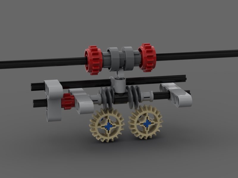
There are a couple of problems with this build. The main issue is that I want to use the output from one or both tan gears (currently just held on with friction pins). They are turning at 1/20 the input speed, which is a really awful ratio.
Also, if there is a way to get the whole thing smaller, lower friction, or both, that would be great.
I don't think any of the above can be accomplished without a totally new mechanism – I think this one is pretty close to optimized (it's about a month of work and help from Reddit user u/Daap72).
Any ideas for a novel mechanism would be greatly appreciated! Improvements to this one are also welcome. Thanks in advance for your help.
[TC21] Technic Transforming Vehicle Contest - Information Topic (Extended to 31st)
in LEGO Technic, Mindstorms, Model Team and Scale Modeling
Posted
TBP got four functions out of one motor. If he can do that, I'm sure you can get four from two!