

anyUser
-
Content Count
192 -
Joined
-
Last visited
Posts posted by anyUser
-
-
Does anybody else also thinks that this will be difficult (not-so-easy?) to take apart without (non-Lego) tools:
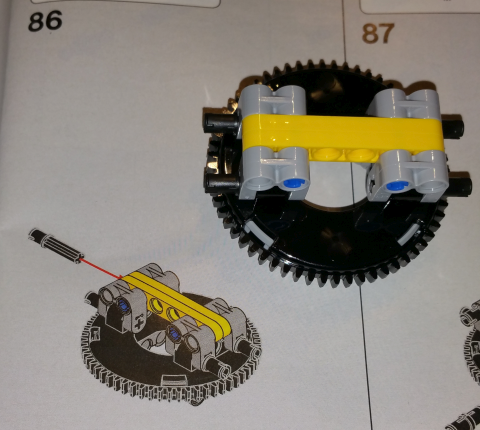
?
-
Many thanks for creating and providing these instructions.
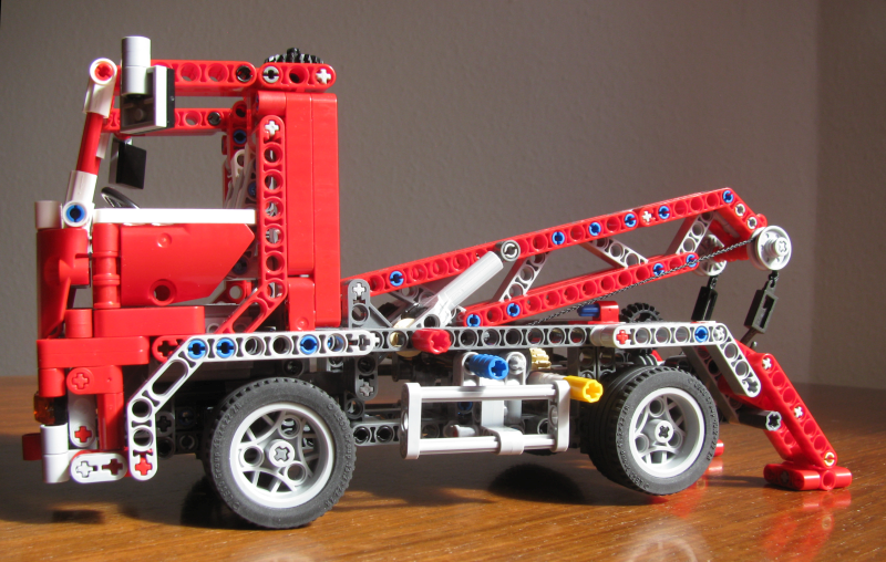
I remember that I built the arm (only) last year from pictures. I then lost interest to build the rest.I have now built the crane in usual Lego colors:
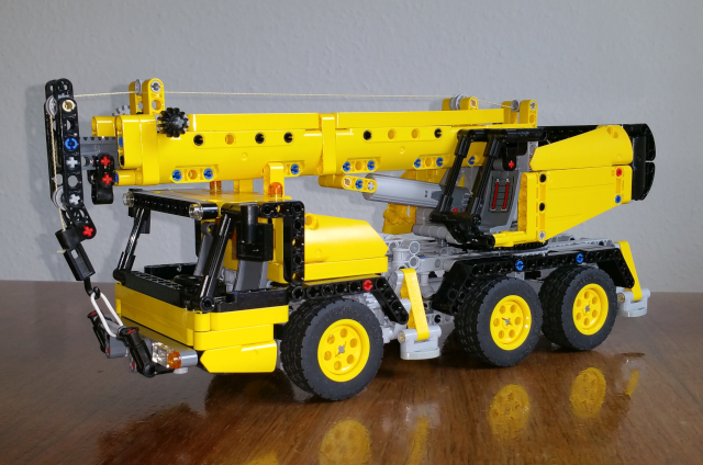
I believe it's very similar to set 8460/8438.
Compared with recent crane 42108 this one is less wide & a bit higher which I find more pleasing: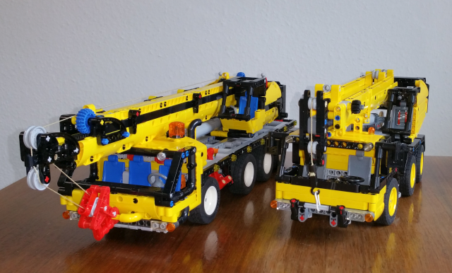
If you do not mind I would like to comment on the instructions (nonetheless):
- Step number in upper left corner is often not recogniseable because of model shown behind.
- Some building steps are difficult to see because they are (partially) covered by box with parts-to-be-used.
See step 234 for example.
- Instruction & parts list does not contain mirrors or steering wheel (cf. step 141: not used). However, it is pretty clear how to add them.Details:
- In step 75 a red 10L axle is used. That did not fit for me. I used a 11L axle instead.
- Before step 52 I would insert the 3L axle pin (32054/65304) before attaching the frame and then pushing it further.
- For step 82 I used part 42195/18948 because the middle hole might interfere with the teeth of the rack.
- I omitted the second 8tooth gear in step 109 because for me a single one had enough friction on the superstructure.
- Adding parts in step 266 is difficult. I suggest not to push the 8L axle-with-stop in step 237 fully.
- In step 272 there is not way to add the second-from-right 3L pin: At this point there is a axle hole in the gear rack.
- tan 3/4 pin from step 61 & 67 are not doing anything and could be omitted.
- The original model has a No 2 panel on the right front of the superstructure: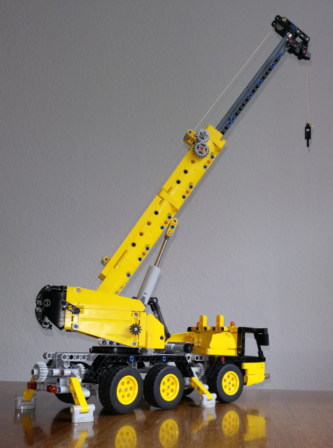
-
1 hour ago, Milan said:As explained, we do not post leaked images with the confidential mark on them, but please do discuss them here

Discussing impressions taken from pictures without being allowed even to refer (link) to them - that does not appear to be reasonable to me.
-
5 hours ago, Lira_Bricks said:Does someone know what the use-case is of https://www.bricklink.com/v2/catalog/catalogitem.page?P=3705b&name=Technic, Axle 4 Threaded&category=[Technic, Axle]#T=C&C=11?
Are those threads to make it easier to pull them out?
The longer ones have been used on turntables together with nuts to fix the upper part of the construction from falling off.
-
On 3/9/2021 at 8:18 PM, suffocation said:Ah, bollocks. I just ordered a boatload of these from B&P - wish I'd seen the pic before finalising my order

I got my order of twelfe a few day ago and those align pretty well. They have different mould numbers.
I didn't open the excavator yet...
-
I wanted to have a versatile platform to build affordable (any resources: parts + time + space) trucks.
- Driving by hand.
- It should have (possibility to add) fake engine driven from rear axle(s).
- No suspension.
- No motorized functions.
- Both 43.2 and 49.2 diameter wheels can be used.So I set up these:
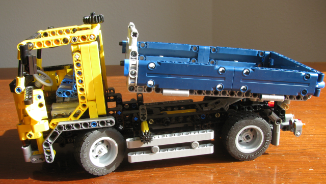
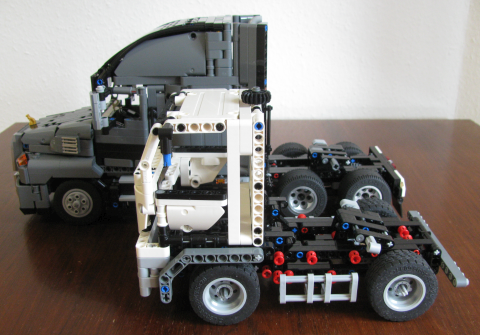
(Cabin design is heavily influenced by set 8052)
From below: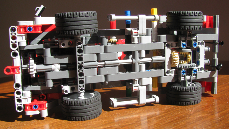
-
On 2/6/2021 at 8:45 AM, Jim said:There will be a final round of answers!
It's been a month since the first/only answer. Do you expect there will be more information?
-
On 12/14/2017 at 5:15 AM, SNIPE said:I have always wondered if this part is compatible with lego technic pin holes.
No it's not.
- the cross section is not a circle
- it only fits the 'collar' width of the pinhole
-
12: 10
7: 6
17: 4
25: 3
10: 2
22: 1
-
12 hours ago, Jurss said:I would remove the bed, then try to look at gears, axles, where motion stops.
17 hours ago, Charlies Pal said:I've taken apart and reassembled twice, with the same result...any suggestions?
I've got a small video that shows the moving parts if you would like to compare:
https://brickshelf.com/gallery/rothw/technic/42114/981_20210211_195058.mp4
-
About the clutch:
The first type of clutch (part 76019) had a range of 2.5-5 N cm written on it. Its - similar looking - successor 76244 didn't have the spec written onto it. According to Brickset database the range would be 3,5-6 N cm.
Last time I used it was in the bucket wheel excavator. In there, it wasn't any good: It slipped most of the time instead of delivering power to the bucket wheel. I think it is well known that the set has friction issues on that part of the excavator. During years I found that the 24tooth clutch would most likely cut the power too earlier. Both motor and gear trains would have handled much higher torque.The new, linear clutch has been added - according to BrickSet database - to four models so far:
Liebherr Excavator (42100), Volvo Hauler (42114), Bell-Boing Osprey (42113), and the Concrete Mixer Truck (42112).
The range given in the Brickset database is 7,5-20 N cm.1. According to the measurements of motor power presented on the Philohome website the upper value would be well suited to the available motor power. The variation of that new part is much larger than for the old one. What is the purpose of that wide range?
2. Another common finding from several forums is that the clutch in the Osprey model wouldn't prevent small gears from getting deformed beyond use.
There is no technical information from LEGO available concerning recommended or proper application of the clutch in MOCs. How should I implement this part in my models: Is it intended to protect the Control+ motors or the driven parts in the gear train?3. Starting with 28tooth turntable some parts that cannot be taken apart any more must be assembled by the customer. This is also the case for the linear clutch. Why aren't these parts put together prior to sale?
-
On 12/20/2020 at 1:33 PM, Anio said:On each side, make the small panels black.
Not quite black (*) but much darker: Forklift version
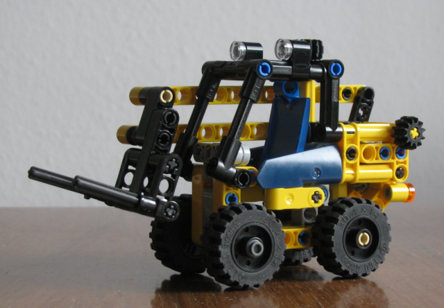
*) My black #21 & #22 panels are either in the Osprey or carry stickers.
-
After Christmas I was motivated and interested sufficiently to improve on my previous versions (drafts). Both mechanism (wormgear respectively ratched) were not robust enough to rotate the drum. I wanted to set up a more solid & strong transmission from drive axle to the function gear box. However I couldn't find a solution that was small enough to fit.
But I got another idea: Use a differential that would accept power from drive train and from (manual) crank instead of gear selector.
From that I could derive several other improvements:
- shorter worm gear set up means that truck has to move less distance before drum starts to rotate (less than 40 cm compared to 50 cm previously).
- Better gear ratio = rotation speed of drum. It is more feasible to replace some of the gears to adjust the 'speed'.
- Secondary drivetrain from gearbox towards rear of the truck & back is not necessary any more.
- Because of that it could be feasible to set up pendular suspension for rear axles as major obstacles are now gone.
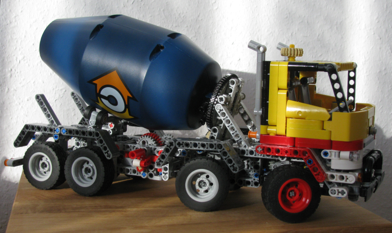
Left side of leatest cement truck version: The manual crank (red) is blocked from rotating clockwise by the red&white lever. This has the cement drum powered from rear axle. Direction of ratation is clockwise (when viewed from rear side).
To enable the crank you flip the lever up.This truck version has small turning cycle and tilting cabin.
(More pictures will follow after upload).
-
11 hours ago, Jgooffer said:.. the rear wheels turn and the engine turns but not the front wheels
My guess is that
a) one of the 12tooth bevel gears is is missing inside the differential OR
b) one of the axles not fully inserted into differential
Thus force would be -undetecably- directly to the idle (not connected) output of the front axle.Did you check if thee differential of the front axle is driven by the motor = rotating when truck is in drive mode?
-
To me the intention remains rather vague: What is the focus = topic that will be addressed by the two sides (TLG Powered Up team and AFOL)?
How much time should be spent?JIm,
are you collecting candidates from this postings to this topic or from personnel message?
Edit: that was a very quick answer. -
4 hours ago, somebricks said:so, any recommendations on where to get started again, with only one set?
May I suggest something else? I consider 42042 Crawler Crane a nice building and play experience. I think it's also a good parts pack.
Otherwise, 42082 has some nice C-, D-, and E-models. (I haven't build any of them but it indicates that the set is a good parts pack.)
I personally am very disappointed by the penumatic arm of the Arocs 42043: there is little play fun in it. -
Hello,
my hauler is not at hand. Therefore i would like to suggest the following tests from another topic on the set:On 11/8/2020 at 9:24 AM, anyUser said:Verify that you have aligned the differentials as shown in step 340 on page 219.
When I lay my hauler on its side and spin on of the rear wheels, the other rear wheel rotates in the same direction and the fronts wheels rotate in the opposite direction. The housing of the grey differential, e.g. the 24-tooth side of it, are visible from the bottom: It does not turn.
(laying hauler on the side effectively blocks the second wheel on the axis and prevent them from spinning.)
On 11/9/2020 at 5:20 PM, anyUser said:If you got that far you could also set up the control+ hub: Put in the batteries (inset on page 222) and connect the cables as described in step 344 respectively 347.
If you start the control+ app a firmware update will be written to the hub. This can be recognized by the red / green / blue changing of the LED. If the hub is ready the indicator will change to a permanent blue. Select the interface for the hauler. It will open in the setup screen to calibrate the motor. This includes a backward / forward test drive. Do not worry: It will take less than the + / - 1 m space. My truck was moving only about 40-50 cm.
The calibation should finish sucessfully even though the linear actuators aren't connected yet. I guess the motor calibration will also work if hauler is (still) laying on on its side. This will give you the chance to see if differentials are moving.
14 hours ago, Jgooffer said:So when I spin any of the rear wheels the engine spins, and the other rear axle spins. Not however the front axle is this 6x6 or 6x4
By "engine" you are referring to the fake 6-cylinder motor in front of the truck? This is powered through the trucks front axles (see step 185 on page 118 (The drive input is added in step 204, p. 132, see inset).
Therefore, if cylinders are moving up and dwon, the front axle should turn as well. -
On 1/5/2021 at 5:37 PM, Gray Gear said:Why dont you just put the Tail Rotor on the other Side? As far as I can see that would fix the problem...
Turning over only the tail rotor to the other side (= rotating by 180°) does not change (the sign of) the pitch angle. Only by moving the 12tooth gear to the right side of the tail the rotational direction will change and therefore, as we are talking about propeller with fixed pitch angle, the direction of the airflow.
I did a check on some parts: 2952 and 4617 have same direction:
- If the propeller rotates clockwise, the airflow is towards the observer
- If the propeller rotates counter-clockwise, the airflow is away from the observer
Of course steph77 is right as a fixed angle pitch tail rotor would do no good any (real) helicopter. The variable pitch angle is used to change the yaw angle of the aircraft during flight.
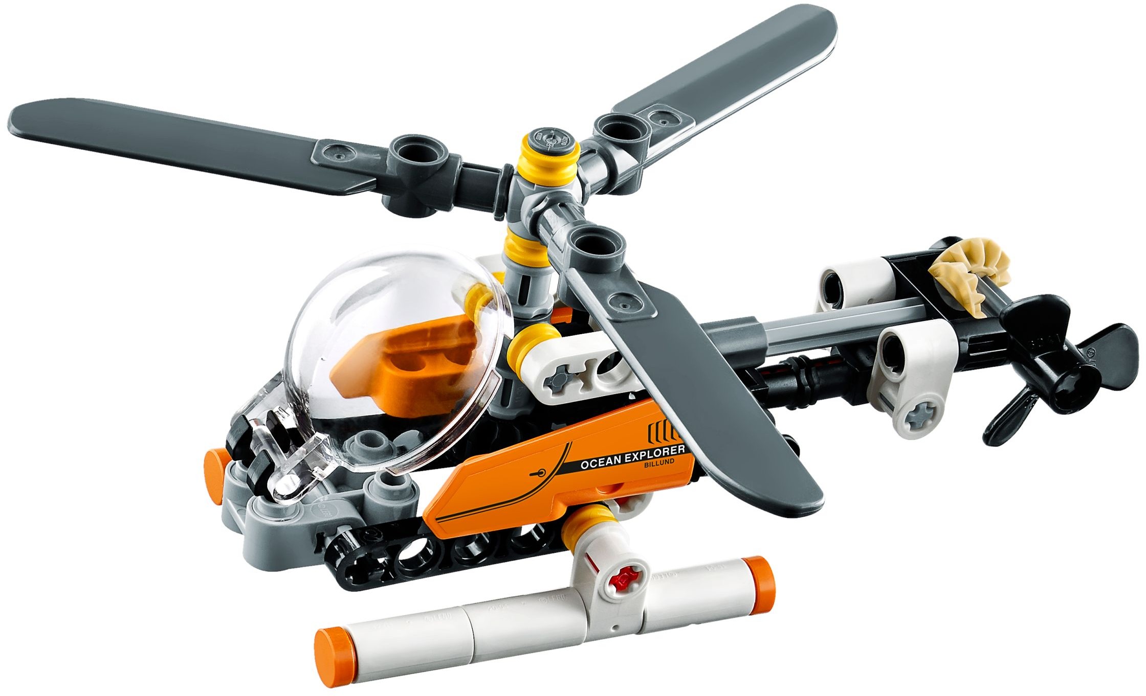
To compensate just for the torque of the (counter-clockwise rotation) main rotor the thrust of the tail rotor in 30465 should be OK (according to the drawings above).
-
49 minutes ago, Gray Gear said:Why dont you just put the Tail Rotor on the other Side? As far as I can see that would fix the problem...
Wouldn't that require the use of panel #21? ;-)
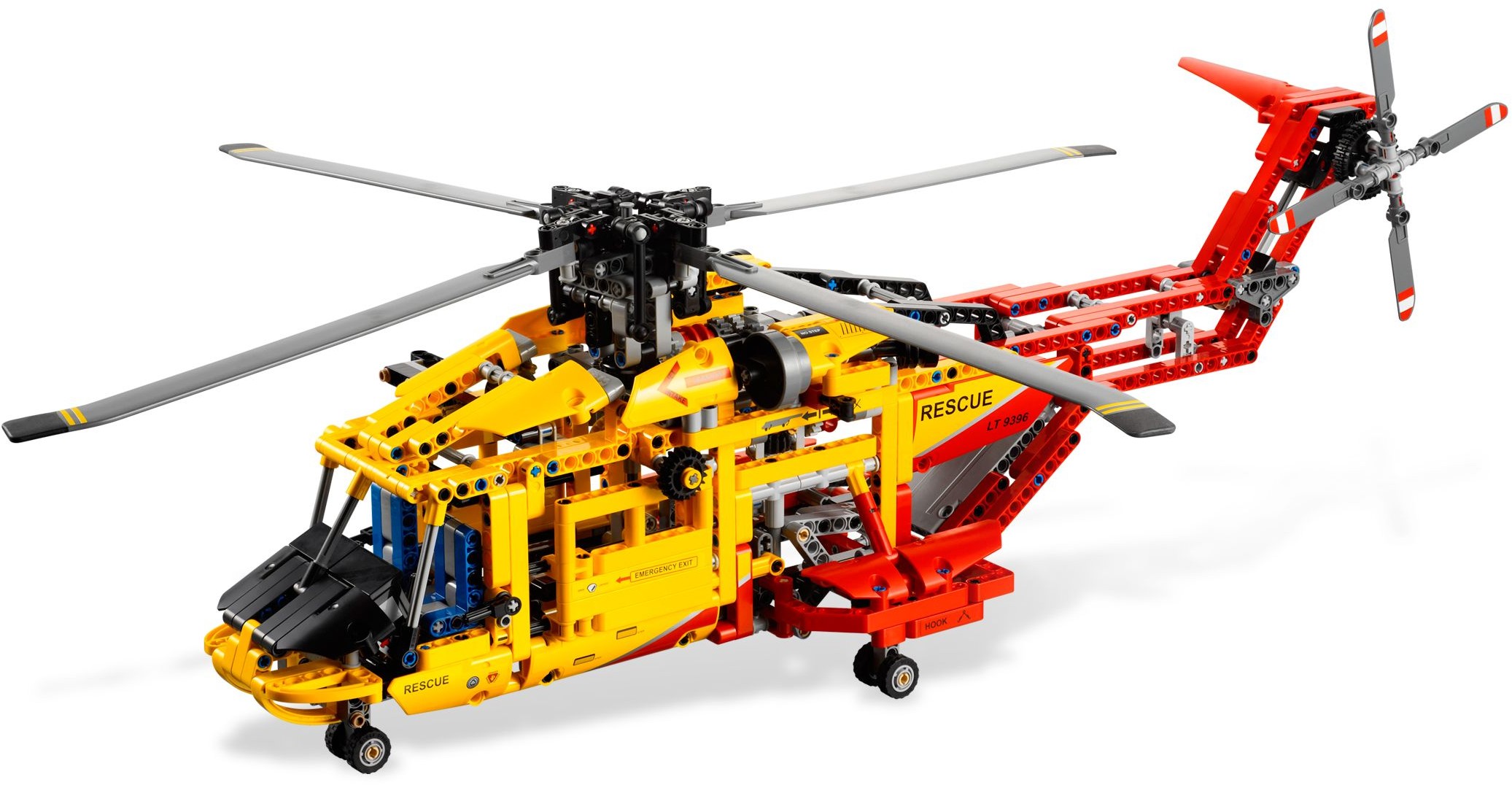
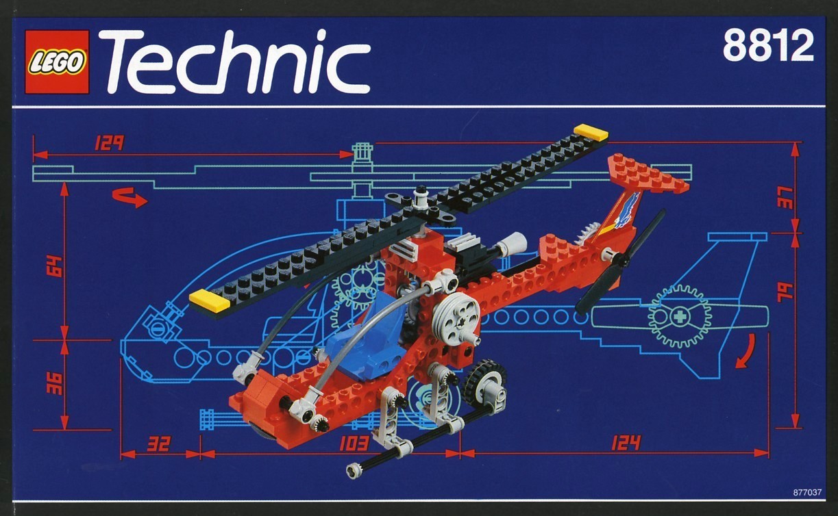
In a quick search i found -only- three technic helicopters where the pitch of main and tail rotor appears to be defined:
Any other one typically does not show (any) sign of pitch on either main or tail rotor. On some models there is no transmission to the tail rotor (8005, 8253).
-
@Sadap: your scheme appears to match the drawing that i found on a wikipedia site:

However, I am lacking knowledge on relation between rotational direction, propeller pitch and the resulting direction of air flow. It may be possible that the tail rotor technically has the wrong pitch.
(But that's not the reason I used a plain piece as propeller in my version).The issue that you brought up should be fixed easily: swap the 12tooth gear in the rear with the half bushing - it may not be the most stable setup but technically more correct.
-
1 hour ago, Maaboo35 said:Another bloody topic on this set! Has anyone been able to get this thing to work?!

Me - but it's just too big to regularly play with it. So I stopped after some test drives.
-
7 hours ago, Jgooffer said:2 dump mechanism works fine
3 drive mechanism not working
...
the drive system works by turning wheels but the power of the motor never goes to the wheels ?
Can you tell if the XL motor turns when in drive mode or does it appear to stall?
(Check gearbox and listen to noise from motor)If the motor is not turning it could be - wrong - alignment of the differentials
-
On 12/20/2020 at 1:33 PM, Anio said:On each side, make the small panels black.
Bright Light Orange + Black would be the perfect color scheme.I was aware that putting in the black panels would give colour scheme similar to the JCB above. Perhaps a few more pieces need to be put in black (cabin + towards the back). But I wanted it more 'friendly', e.g. bright.
I have most of the available parts in Bright Light Orange - but some just haven't been made. -
my attempt on black & yellow version:
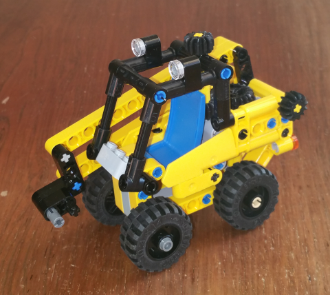
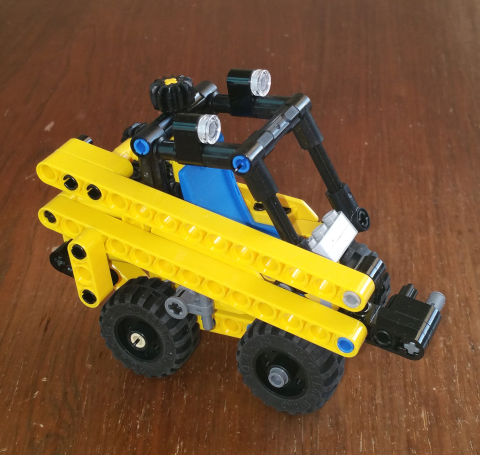
Conversion into a fork loader seems feasible.
[REVIEW] 42121 Technic Heavy Duty Excavator
in LEGO Technic, Mindstorms, Model Team and Scale Modeling
Posted
Thanks for your suggestions. I didn't think about assembling a tool = using more than one part for deconstruction.