TheQ
-
Posts
57 -
Joined
-
Last visited
Content Type
Profiles
Forums
Gallery
Everything posted by TheQ
-
Finally after 2.5 years of planning, modeling, source image finding, photographing, purchasing and building, I can finally present to you Downtown of Oulu, Finland in microscale. This 1.5 m x 1.2 m large creation contains 6 city block x 7 city block chunk of the finnish city Oulu containing following "well known spots" of the downtown and water front area: Theatre Main library Market square with tents Old market hall Toripolliisi ("market square policeman") status Rotuaari shopping area City hall Scandic City hotel Radissons SAS hotel ... and bunch of other sights familiar with local people. As for the technical details, creation is build from roughly 30.000 bricks and it was designed using city's online map resources, Google Maps, Bing maps (helicopter images helped a lot) and tons of legwork. Design can be found from Stud.io gallery. Feel free to download the model but do note that 3d model is not yet final, it is missing the "waterfront" area and final supports. I have also older versions of the city in Stud.io if you are interested in the progress of the city. More pictures of the creation can be found from Flickr gallery.
-
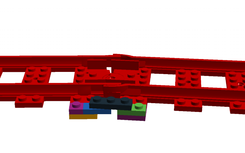
@Roadmonkeytj Here is a simple breakdown of the wagon separator / decoupler mechanism: The 1 x 5 beam is lifted and set between the wagon wheel sets and when it is up, the wagon stays there. The trick is to fine-tune the magnets: If you have too strong power (two modern magnets), the train engine will only pull itself away. If you have two little power between wagons (two old magnets), train engine will pull few wagons with it but others way stay with the separated wagon. Best combination for me was using old and modern magnet together, that let me separate any wagon in a four wagons long train.
-
I have built remotely controlled Inglenook-layout: The layout worked nicely and I did some shunting puzzles during events but as running a demo puzzle took some time to do + not many visitors were big fans of trains, I didn't do many demonstrations during displays. The basic shunting did work well tho, and it was nice to be able to remotely control train engine, switches and wagon separators. I used SBrick to handle the manipulation of the "ground mechanism". In the topic you can find link to Youtube video where I display them better.
-
Took me a long time to finally update this thread but yes, the Inglenook-layout was finished and it was successfully displayed in three LEGO events. In each event the layout worked fine, only issues I had was with SBrick: it requires quite sturdy power connections and if power connection does not provide power all the time (for example, voltage moves between 9v and 7.5v as the case was in really, really large event places where thousands of machines were using power), the SBrick tends to restart itself which causes the whole software to halt for some time. It seems that under 7.9 the machine tends to restart which usually required me to unplug the 9v train controller that I used. It is possible that the issue has to do with 9v train controller but even if I changed that, same problem occurred. Anyway, the main functionalities, remote handling of switch and remote wagon separation, worked generally really good. The wagon separation did require some tweaking since I had to find magnets of right strength for the train engine to be able pull three wagons but still for the separation mechanism work for wagons. This created some challenges as separation sometimes caused extra wagons to be stuck with separated, stopped wagon. Here is short demonstration of the remote switch and remote wagon separation taken with bit better camera: Youtube
-
Very, very nice work. I love these layout building topics where people take time and care to build their scenery. This thread has been one of my favorites for a long time now since it combines planning and actual implementation pictures!
-
Here is the folder which has images of basic road structure: http://www.brickshelf.com/cgi-bin/gallery.cgi?f=458362 (descriptions in Finnish, sorry). It is quite similar to Michael Gale's MILS MultiRoad and Mike Gallagher's roads. Most notable difference is that our LUG's roads do not use baseplace.
-
Very elegant solution! I am very keen on experimenting with this one. Is one brick's width deep enough to anchor the guiding arm well? In my LUG, we use two bricks wide roads on their side and if one brick's width is enough, the guiding arm could be hidden even better. I have some experience on getting cars to move on their own but my solution was based on train track hidden underneath the road. That caused the minimal ring of the self-moving car to be quite large and high. This solution seems very nice, alhough it requires also some space in the corners.
-
Technicopedia
TheQ replied to Blakbird's topic in LEGO Technic, Mindstorms, Model Team and Scale Modeling
I don't really know how Technicopedia is built but would a Varnish or similar external caching software or even CDN (content delivery network) help to alleviate the bandwidth issues? The site itself is a treasure trove for TECHNIC fans old and young and it is sad that we cannot have access to it all the time. Oh and I have been following Technicopedia since second or third "update" and it has been always one of those sites that I recommend to new TECHNIC builders. Your work is marvellous, Blakbird! -
Bigger image available at Flickr After around one month, the layout has seen some progress. Major changes are: Added missing module on left corner and changed the modules a bit so that the complete layout is now 8 x 2 modules. Added third wagon separator in the middle track to allow wagons to separate at right places according to Inglenook puzzle. Finished with the initial plating of most of modules. Added "maintenance/service area" Most importantly, decided on the theme and layout of the creation! I decided to go with sub-urban passanger station as another guys is building larger train station elsewhere on the layout. Next up is setting up the PF motors to handle all five functions (2x remote switch, 3x wagon separators) and then building the railway station above them.
-
Yeah, Electricsteam is right. The ground level is around 2 bricks so only place close to track where I could move the motors is underneath the track. That would mean buying quite many extension cords which I don't really need so I opted for using axles to transport the power to switches and decouplers (heh, I thought there was better term than "wagon separator ). As for clutches, I am using two designs: this one made using two "Technic, Pin Long with Friction Ridges Lengthwise and Stop Bush" and this one made using two axle's with pins on the end. Both of them work quite fine, althought the switches use a bit of power so finding the right "clutch level" is a bit difficult at times.
-
Hi all! Inspired by all the fantastic train layouts here in Eurobricks, I wanted to build my own train layout. Since the finnish LUG, Palikkatakomo, is going to have big exhibition next April, I wanted that the layout could be integrated to large city layout we are doing there collaboratively and thus, the layout should follow the modular standard we use. And as bonus challenged, I wanted to try my hands at remote controlled switches and remote controlled wagon separators. Bigger picture avaiable @ Flickr You can see the layout's current state in picture above. It is currently 2x7,5 modules large (single module being standard 32x32 bricks) and consists of outer 9v track as "mainline" and inner PF track as yard which is designed after Inglenook shunting puzzle. Layout is quite simple but interesting things here are switches and wagon separators which are controlled by PF motor in the left corner. PF motors are controlled by phone via SBrick bluetooth-connector. Both switches and separators work in the same principle: PF motor turns axle that is connected to bunch of other axles, i.e. drivetrain underneath the "ground level" (1 brick + 2 plates) which is then connected to small linear actuators. These actuators then either move lever that is connected to switches "track selector" in or move lever that pops a "stick" above tracks; this stick can be used to anchor wagons and thus allow train to leave wagon(s) behind. Oh and note that aforementioned drivetrains are built in such a way that each module can be separated from each other in order to ease their transportation. If you are bit puzzled on how this all works, please check this demonstration on Youtube: Next steps for this layout project is to make the layout bit larger (aiming at 2x8), strenghten the modules, possibly add another wagon separator bit on third PF track and figure out what else to build on this layout. Currently I am leaning towards "custom car shop" that gets the steel it uses via trains..
-
I do not have experience on MILS but our LUG uses very similar module (no baseplate, framing done with TECHNIC bricks, bit higher than MILS) and we have noted that in larger creations there is no need to use pins everywhere. If pins are used everywhere, assembling and disassemling anything larger than 3x3 becomes a chore. We usually "pin in" only the sides and corners of larger creations, plus some sections crisscrossing the whole assembly (like roads in city made out of 100+ modules).
-
Based on my own experience, I would even go so far that I would add inverted 2x2 roof bricks on the bottom of the black 1x2 plates shown in Sin's picture. This would make it easier to find right spot to place the plate since the inverted slope bricks would provide a guide to correct spots. Small addition but it really helps when you are moving things around.
-
Hi all, I have been recently working on some track layouts and I have grown to like the flex track, even if it is flimsy. My major problem with the flex track is that it is hard to lock it to certain angles. The 0 degree angle is easy to make, just but 2x4 or longer plate in the middle but other degrees are harder to achiece. I recently come up with solution for one locking technique that locks the flex to around 6,5 degree curves, i.e. the max curve. The technique of course requires bit more bricks to make the connection stable but you get the idea. I would like now to ask for other techniques that you have either come up on your own or found online. I did some google-fu but didn't really find any solutions but I think others have come up with brilliant solutions already. So, why don't we make a small info and idea thread about locking the flex track?
-
"It's a common day at the busy port of the village. A new shipment of gold from local mines is now being stored to the village's fortified storage hall and the King's guards are more watchful than ever. This doesn't cause any problems to the boat crafter who lives and works close by; he more than enjoys peace when he is working on a boat. With his son's and brother's help, he is soon finished, right in time for the meal!" Finally had a moment of time to "publish" my most recent MOC. This medieval harbor scene was built as a small part of larger display that was shown in LEGO event around a month ago here in Finland. The whole event was very successful and we had a lot of people looking at our LUG's display. This harbor that I built consists of two main buildings, the boatyard on the left and the fortified storage hall with the harbor on the right. The idea behind fortified storage hall is that it is a temporary storage area for cargo and that it has both wagon station and horse wagon station so that the cargo can be easily moved from ship to horse carriages. Hopefully you like it! More pictures at MOCPages, Flickr and Brickshelf.
-
A scene from old SNES game "Gundam Wing Endless Duel" which I built for MocAthalon 2013. (If you are not familiar with the game, .) The creation was made for the category "It's me, Mario" where the idea was to build a character from a videogame. In the creation, you can see Mercurius and Gundam Sandrock facing in other in a scene inspired by "Wing / Wing Zero stage". I first thought about building that cool "rising horizon" background to the MOC too but due the tight schedule, I had to leave it off. Still, I am quite happy with the outcome, especially the mechas come out quite nicely. This was my first time building such a small mechas which proved to be fun challenge.More pictures available at MOCPages, Flickr and Brickshelf.
-
Review 70000 Razcal's Glider.
TheQ replied to Cardinal Brick's topic in LEGO Action and Adventure Themes
After buying this set, I really can't say that opinion of it has improved: It still looks like odd pile of strange parts. The set does have some neat parts ("beak", wings and those awesome printed 1x2 tiles) but still, the completed set looks like it was just first draft, not the final version. It has some good ideas but the execution is just lacking. Of course, if you are into the fig or the whole theme, go ahead and buy it but if you are uncertain, I recommend checking out the part list to see if it really is worth the money. -
This miniland-scale snowmobile was built for our LUG's, Palikkatakomo's, mid-sized winter contest. The theme was, naturally, winter and for some reason, my thoughts went to snowmobiles. I didn't really design this snowmobile after any specific brand or model, it just more or less was built after seeing different pictures of snowmobiles found via Google image search. The colorscheme of the driver and snowmobile was also just imagined, althought the driver's outfit looks quite similar to the traditional "tourist overalls" that you can see in every Laplandish snowmobile safari. Helmet was inspired by snowmobile and motorbike helmets and accidently it came out as something similar to Spartan's helmet from Halo game series. Last part that I added to the creation was the surroundings which are kinda usual and nothing out of ordinary. Only special things that I tried to do was to add some "crushed snow" behind the snowmobile's skis and tracks which works quite Okay (not ok-ey), althought some improvements could be made, naturally. I am quite satisfied with the build and especially with the building process: It took me only 6-7 hours from start to finish which, for me, is extremely short. More pictures at Flickr, Brickshelf and MOCPages. LDD file is also available via MOCPages.
-
Small TECHNIC forklift project
TheQ replied to TheQ's topic in LEGO Technic, Mindstorms, Model Team and Scale Modeling
As far as I have tried, the connection is quite stable and strong. Naturally, I have added frames around that so that the stud-axles are always compressed. Actually, sometimes I have opposite problems: The connection is too strong and the stud-axles have a bit of hard time moving around! -
Small TECHNIC forklift project
TheQ replied to TheQ's topic in LEGO Technic, Mindstorms, Model Team and Scale Modeling
Carsten, I used following bricks to make the clutch: + + - Pins are put inside the round hole. One axle is connected to the small linear actuator and another one is connected to the gearbox's stick. It works quite nicely, althought sometimes it requires some tinkering to loosen the connection a bit. -
Small TECHNIC forklift project
TheQ replied to TheQ's topic in LEGO Technic, Mindstorms, Model Team and Scale Modeling
Here's small video I took to explain the functionalities of the creation bit more. I was bit lost at words so I did not add too much explaining text to the video. Hopefully you can still get the idea how it works! And no, I did not take video of it moving around as I am not satisfied with the movement. Please also remember that this is still in WIP stages and thus there are many "errors" in the creation. Still, this video should explain the concept of the creation. PS: Sorry for slight light flickering, my "studio lights" are getting a bit old. -
One Way Drive Clutch
TheQ replied to clarkdef's topic in LEGO Technic, Mindstorms, Model Team and Scale Modeling
I think one of the most used technique is "ratchet" mechanism that was talked about in . Basic concept in that is to engage or connect the gears when they move in one direction and disengage them by letting some gears to "jump" around driving gear when the forces are used applyed to other direction. There was good picture of that mechanism but there are also some pictures available. -
Small TECHNIC forklift project
TheQ replied to TheQ's topic in LEGO Technic, Mindstorms, Model Team and Scale Modeling
The actuator does move. There is simple clutch between it and the stick of the switch ring that allows actuator to move while making sure the stick can just move around 90 degrees. The clutch is made out of two 6587 Technic, Axle 3 with Studs and Technic, Axle and Pin Connector Angled #1. As far as the functionality of the steered wheel goes, it works like this: After the wheel is maximum position (say, 65 degreed to left), it stops. Since it hits "dead end", it cannot move to that direction any more. However, differential is then engaged and it starts turning. The differential moves the gears that are connected to actuator moving it and also, via the clutch, they move the stick that controls the switch ring. However, stick can only move around 30 degrees to certain direction until it is stopped. However, the actuator can finish it's movement because the clucth does not have any effect on it at all. I definetly need to get a video that will explain how it works -
So, time again to start a new project. After getting some inspiration from Lasse's work, I wanted to also create something small and usable. My idea was to create a small forklift that could be fully remote-controlled and that would fit in the Model Team Lasse uses. However, after I tried to squeeze the necessary gearing into that small area, I noticed that it was really tought and while the whole thing could be done, it would look awful. Thus, I wanted to upgrade scale a bit and widen the structure by two studs. After some tinkering, I was able to design following: What you are seeing is the internal gearing of the forklift. Basically, there is four functions (let's call them F1-F4) that are controlled by two motors (M1-M2). General concept of the creation is that the M1 can control which function M2 is powering while also powering it's own functions. To let you readers understand bit more what's going on, let me elaborate: M1 (dark purple) is responsible for handling two functions, steering (F1 - the rear axle - green gears) and tilt (F2 - small linear actuator - light purple). When F1, i.e. steering, reaches maximum angle, the differential right infront of M1 starts to move. It runs the F2 and also, via small clutch, the gear changer that is infront of M2. F2 can therefore run indepently from the gear changer. M2 (light purple) runs either front axle drive (F3 - front axle - blue parts) or lift (F4 - drum roll - lime parts). Since F4 is sitting on axle with stud on the end and the stud is sandwiched between holes, F4 can stay in one place under small load. This picture from under the gearing may also help you out. After finishing with this LDD design, I made brick-version of it to get some real usage experience: I am fairly happy with the design althought few things came up after using it over one weekend at LEGO event: Current rear axle is not really working as sometimes it drives over the "guards" that I have built in. When that happens, the whole thing stops working as the engine cannot produce enough power to free the axle. I think the best way to get rid of this is to change the rear axle to standard two-wheel axle. That would make it simpler to build stronger guards. Since I used M-engines, remote-controlling the vehicle takes effort to learn since everything works on super-speed. You need to be very careful not to "overdrive" any functions. For example steering and driving is hard since the vehicle responds like annoyed little chihuahua, only using max speed and maximum turning angles. I think switching over to XL engines would be useful since that would slow everything nicely. Of course, adding extra gearing is also possibility but somehow I feel that XL engines would be better bet. More pictures at Flickr and Brickshelf.
-
I think the video Alasdair sent is good introduction to the concept of limited slip differential (LSD) but as far as I can see, it doesn't really tell how LSD was used in Lasse's truck. In Lasse's truck, LSD was basically used instead of differential to do the same thing: to allow wheels to turn at different rates. The easiest way to see the difference is to compare this step from previous truck (Scania Highline) to this step of the new truck. In the previous truck, the axle was set up so that the wheel on the left side was directly connected to the axle but wheel on the right side was connected via friction pin with bush in the end. In this way, when the axle turns, it forces the left wheel to follow the axle movement but the right wheel can slip a bit from the movement. Hence, it's limited slip differential. Hopefully this explains it. If you still don't get the idea, try it with real bricks and you will notice what I meant, hopefully.