
Nelson
-
Posts
70 -
Joined
-
Last visited
Content Type
Profiles
Forums
Gallery
Everything posted by Nelson
-
 Cool! I've been occupied with repairs to my condo, but that's wrapping up. Once I get back from my upcoming vacation, I'm planning on getting back to my model.
 -
@BrickBear It's alive! Great to see it scooting along. What's next? Is there a way to get the legs up off the ground a bit more? Maybe control that front leg splay?
-
Sorry I haven't checked in recently. Looks like you're still making progress, @BrickBear. A couple weeks back, I did work on a version of my old chassis design, combining it with the newer, more direct motor and drivetrain designs from my later chassis. Unfortunately, I ran into issues where moving parts are hanging up at various points in the cycle. This has been something I've encountered often and it can be tough to predict. The smallest .025mm ridge between two "flush" mating parts is enough to catch a rotating liftarm and bind the whole mechanism. I'm getting a few parts on order to combat this. Sometimes it's as simple as using a part with a rounded vs. squared end so that the liftarm is subtly directed over that catch point. Other times, it means reevaluating the whole design. Have you encountered this issue? It can be challenging to create clearance areas when the available space is so limited.
-
@BrickBear All good advice, especially the bit about trying some smaller models first. I'm in no hurry. I'm using Studio at the moment. Would you consider that the best option or have you tried others that are better?
-
@BrickBear My hope is to offer it as both instructions or as a full set. I'm not sure how many sets I'd put together. Some of the parts I'm currently using are out of production. I'm hoping I can make design updates to get all the parts current, but that will be challenging. I received an insane amount of positive feedback and requests to make the instructions available after I posted a FB video of the current design taking a few steps. I think I could easily put together a dozen or so sets and there would be ample buyers. But first things first. I need to actually finish the thing! And generating instructions will be no small task. I'm easily a year away from putting anything out there. I'm also stocking a new BrickLink store, so lots to do.
-
I put together a new version of the "slide piston" chassis over the weekend. It answered my question about one motor being enough...I believe it is, even with the slightly taller gearing I used. Unfortunately, because of the design modifications to accommodate gearing change, the build was not as rigid and wasn't an overall improvement. I've made up my mind that I'm going to try my older mechanical concept with the newer drivetrain style. I think that the older concept has a more accurate walking motion to the film and fits within the body better. The drawback it that it's more complex and touchy than the newer "slide piston" concept. Considering my end goal is to sell the MOC, this is a risky decision. But if it ends up giving more accurate motion and aesthetics, it will be worth it.
-
Glad to see you're still at it. You're going to have to post some video sooner or later, even if it's to see where the movement is falling short. I'm dying to see the shuffle! You hung onto the bending knee dream a lot longer than I did. I hope you're able to get that working once you solve for the other issues. I just received a part order and will hopefully get a new chassis together this weekend. It should be a bit faster than the last, have better clearance from the piston rods that were grazing the upper part of the legs, and possibly offer some better timing so the rear and front legs don't have overlapping cycles. Or it could just fall over. Who knows? I've also been working on my head design, knowing that I should get that integrated sooner than later. I'd hate to have a working version that is set back to zero because it can't accommodate the head weight. I also wonder if I could get away with only using one motor.
-
@BrickBear Glad to see you're keeping at it and have made some progress. I'd love to see your model fired up, even if it just shows what challenges still need to be addressed. I've been trying to parlay the success I had with the more direct motor position of the slide piston design into a new chassis based on my earlier mechanisms. The gait was more correct with that old design. It just struggled with flex and lag in the drivetrain. Unfortunately, creating a combination of the old mechanics with the new motor position is proving very difficult. I just received a new pair of large Powered Up motors so I can keep the slide piston design intact since it's actually working pretty well. I put a short clip of it walking on a Lego Star Wars Facebook forum and have had a ton of positive response. Perhaps I'm being too picky about way that model walks and should keep fleshing that design out.
-
@BrickBear That's a neat idea. I wonder what adding something like that to the feet of my model would do. I have a bunch of those rubber parts. Did you call them "cheese wedges"?
-
@BrickBear Any progress? I haven't had a chance to do much with my design lately. I did try a few other settings with the flex range of the ankle, but ended up back where I was for the test in the last video. I'm planning on eventually ordering a second pair of Powered-Up large motors and reviving my older design but with a more direct drivetrain. While this version is the best working I have built to date, I'm not 100% happy with the slightly off cadence of the steps due to the geometry of the mechanism. Hope you're feeling better and can get back to destroying Echo base!
-
@BrickBear I had an enlightening result from my attempt to add a bit more ankle flex. The whole design almost completely failed when I added even the slightest bit more range. Previously, the foot could only flex about 2-3 degrees at the ankle. I bumped that up to about 5 degrees and suddenly the model pitches heavily toward the lifting leg, nearly falling over. It sounds a lot like what you're experiencing in your design. Maybe try an experiment where you make the ankles of your model quite rigid, just a couple degrees of range. I'm curious to see if that negates some of that leaning you mentioned. I was not expecting that much difference...or any difference really. It was quite surprising and counterintuitive. I would not have suspected that a joint perpendicular to lateral stability would have such an effect. I guess that stiffness was a key component to my current model's success. Looks like I'll be putting it back the way it was. I'm trying to decide if I'm satisfied with the way this version walks. It's certainly not perfect, but it's closer than Lego's version. I'm going to do a few more tests this weekend, then put it on the shelf for a while. There are some other projects calling and I need a break on this. I'll keep checking in on this thread to see how things are progressing.
-
Interesting idea, but I think I'll explore other options for now. There is only about 2.5 studs worth of lift happening between the foot and the ground. I think a system like that would negate a good percentage of that clearance. It would also be tough to keep the ankle struts' functionality working. Aside from looking accurate, those bars are critical for stability.
-
@BrickBear I'm not following. Are you saying the whole foot would be attached via springs? Would the overall length of the leg-foot assembly vary as the springs compressed and relaxed? I don't see how that would work. It seems like it would introduce a slew of other issues.
-
I made some adjustments to the cam contact areas and got more lift. This helps the inside "toe" clear the ankle stabilizer. I may make the toes hinged so they clear better and look more accurate. (I had that feature on an early model.) I'll just have to see if it compromises stability. The cadence is still a bit off. I'm pretty sure this is a result of the mechanism's geometry being imperfect and the limited range of the ankle joint. The rear foot can't flatten out when the leg comes down because the ankle only has a flex of a few degrees. This is a fine line to get right. I could try to get a bit more flexibility range, but then risk the walker falling back on its rear. (I believe @BrickBear was experiencing this phenomenon.) I think the next step is to try and add some body panels and a rudimentary head so I can see how the design handles the weight and balance changes. There's also the issue of the legs which begin to split apart after a while. I'm bummed about that. I spent a massive amount of time getting these legs designed (with strength in mind) and I feel like the options of build styles I have for getting better longevity will compromise the ascetic. But hey. That's part of the challenge.
-
If there's one thing I know how to do, it's take a design that's functioning at 70% and make it function at 25%. All my attempts at correcting the issues with the recently posted design have yielded worse results. I think the reason the rear legs are a bit too forward in timing is because I have to use 44809 pin connectors everywhere. It causes the geometry of the rotational centers of the slide piston mechanism to be a stud off center in some areas. I don't know why LEGO doesn't make a pin with pin hole (15100) without friction ridges. That would be so useful! With the front and rear mechanisms being flipped mirror images of each other, that subtle offset compounds to make the lifting motion a bit late on the front and a bit early on the rear (while the cams remain timed correctly). It throws everything off just enough to be annoying. I'm rambling. I'm considering going back to elements of an earlier design but keeping the new motor/drive setup. For a long time I thought there were other issues at play, but now I see just how much of my failures were caused by the flex and power loss in the drivetrain when I had all those axles connecting the motors to the cranks. Maybe by combining the new with the old, I'll get it right.
-
Another chassis update. This one eliminates pretty much all of the slack and flex in the drivetrain with two motors directly driving their respective cranks. Still a ways to go, but this feels like a major step forward (pun intended). Update: I’ve been tweaking and tinkering for a couple hours now. It’s the first design I’ve built that can keep walking without the mechanisms self destructing in a few steps. It’s revealing other weak points that weren’t apparent before. I think I’ll need to redesign the legs. There’s an area in the shin that eventually separates after about two or three minutes of walking. I’m still really thrilled with this progress though.
-
@BrickBear I believe having the legs laterally stiff throughout their cycle is essential, at least in my design concept. I gave up on the bending knees early on in favor of stability. I admire your efforts to include that functionality. If you succeed, I will certainly consider adding it back. My hope is to get the appearance of bending knees by having the upper portion of the leg be a sort of hinged box around the straight liftarm inside. I'm not exactly sure how I'm going to control the movement of that upper leg. I'll burn that bridge when I come to it.
-
I decided to try a different drivetrain configuration. Instead of the rather long path of having the motors positioned below the body going to a worm gear, then up through the body's center into another gear reduction, then along the length of each forward and rear half (whew!), I put the two large motors at the top of the model, directly driving a 40-tooth gear via worms. I was concerned this would make the model too top-heavy, but with the battery box moved below, the weight distribution is about the same. The first run was promising, but as expected, the cams worked themselves free of their drive gears pretty quickly. Still, this is promising. I can solve that issue by adding supports around the cams, but then I run into problems where the width of the internal mechanisms are outside the boundaries of the bodywork in the final model. I'm working on a new design that will deal with that and will hopefully have it tested this weekend. You can see when the rear cams become disengaged in this video. You can also see that I need to add a bit of assist (probably a mildly tensioned rubber band) to get the rear legs down.
-
@BrickBear I'm guessing you've already referenced this site, but it's always good to put it out there for folks to check out. https://www.philohome.com/motors/motorcomp.htm I'm not well versed in how electric motor power is rated, but I can say that, in my model with two large Powered-Up motors, the weak points are the gears, axles, and general flex of parts, not the power. I really like the gif of your chassis. I'll be jealous if you beat me to a full working model. I will say that I had a very early chassis-leg version working a few years back that used springs in a similar fashion. Unfortunately (as seems to be the Achilles heel of all my designs), the springs could not deal with the weight once the full body cladding was installed. Perhaps your bodywork will be light enough. I replaced the broken gears on my most recent design, but couldn't even get it to take a single step the next time I fired it up. The gears jumped immediately. Weird how a design can work one day and fail the next. I've come to realize that, with the margin of success and failure so slim, wear and fatigue on parts can make a big difference. IE: In my model's drivetrain, I have a fairly long run of axles that connect the motors (slung underneath) with the final leg mechanisms. The flex of this drivetrain can get pretty severe. There are times when two legs can almost be on the same cycle if one binds up. The power continues to drive the other legs until the flex of the drivetrain reaches its limit and everything grinds to a halt. I've noticed this effect grows worse over time as the axles are flexed over and over again. Eventually, they lose a good portion of their integrity even though they don't break. It may be worth rethinking my overall layout in order to get the power output and the leg mechanisms connected more directly. I think I'm going to give this "slide piston" version another go. I want to add some rollers for the cams to contact against. I think the friction between the cams and their contact points is creating too much resistance now that I have some rubber bands assisting the lift. It's interesting that I have rubber bands pulling up that need to be overcome on the downward motion while you have springs pushing down that need to be overcome on the upward motion. It's definitely a tough battle to fight from either direction! I'm concerned that your leg lift times overlap too much. It appears that the front leg hasn't completely come down before the rear leg is coming up. What if you left a bit of gap between the rotating liftarms and the lever? Maybe use a 4-length and 3-length liftarm instead of a 3 and 2, but have some space where there's no contact?
-
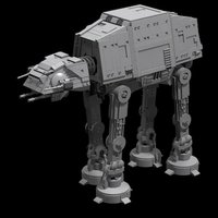
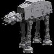
I incorporated the slide piston design I posted earlier into a full chassis and it actually worked fairly well. There may be some promise in the concept after all. Unfortunately, it only walked through about 5 full cycles before a tooth broke off the main gear transferring power to the leg mechanisms. It's a real pain to change it out, pretty much a full disassembly. I'll try to get to it tonight and get a video up soon. AT-AT Slide Piston Design by Nelson murray, on Flickr AT-AT Broken Gear by Nelson murray, on Flickr
-
Well. I worked up a few more designs, one using Power Functions XL motors, one using large Powered Up motors. I experimented with a piston-style lifting action rather than the liftarm method I've been using. Nothing improved the functionality. The XL motors were overkill. Two large PF or Powered Up motors are more than adequate using worm gears. The piston style lifting motion still had the same issue as the liftarm where it flips though the lift cycle too quickly because of flex in the drivetrain. The lifting action gets backed up then jumps through to the end of the lift rather than creating a nice smooth lift and set-down. The one new bit of info I discovered is that the cams don't need to hold the leg in the down position for 3/4 of the cycle. They really only need to hold downward pressure for 1/2 the cycle. The key is to have the legs across and behind the lifting leg supporting the model while the one on the opposite corner is unsupported. This makes it so the walker is only supported by two legs at a time and the one on the opposite corner of the one lifting isn't inadvertently pushing the model over toward the lifting leg. Here is another design I'm going to try. I'm calling it the "slide-piston" design. It also will probably not work.
-
This version uses a crank/piston-style lever inspired by the @BrickBear designs (the red connector with the black axle) to move the leg forward quickly, then back slowly, rather than trying to get the lifting arm to accomplish that lateral motion as in my previous models. This version also incorporates a new cam design that releases the downward pressure on the leg opposite the one lifting. This means the model is always balancing on two legs rather than three (even though three are still in contact with the ground). This helps to level out the overall balance and prevent the walker from leaning toward the raised leg. These ideas show promise, but are not without issue. The crank/piston lever needs to move the leg further than this to actually propel the walker at a reasonable rate. The lifting mechanism is (still) underpowered and jerky. Perhaps it's time to get a couple XL motors into the design and maybe try a piston-type lifting action rather than this lift-arm lever design. Also, when I attach the real legs, they're too heavy for the mechanism to move effectively. Still, this feels like progress.