


BrickTronic
-
Posts
110 -
Joined
-
Last visited
About BrickTronic

-
Hello, Assumptions are : Inactive : both lines low shift in "1" : Set upper Line from "0" to "1" and then back to "0" while lower Line remain "0" shift in "0" : Set lower Line from "0" to "1" and then back to "0" while upper Line remain "0" Strobe : at last Bit set upper or lower Line from "0" to "1" while lower upper is still "0" but then set the 2nd Line also to "1" At end of sequence set both Lines back to "0" The CLK of the Shift-Register is delayed by the OR-Gate. so that Data-In of Shift will be stable If necessary 2nd OR/AND Gate (with 2nd Pin wired to GND or VCC) secures sufficient propagation Delay If you use 74LS595 or CD4094, then the OR is wired to Shift-Clock and the AND to the Strobe-Clock When using 74LS164 with 74LS273 then the OR clocks the 164 and the AND the LS273 Both circuits can handle 8-Bit, in drawing I was lazy and draw only first 3 Bit Jo
-
Hello, A possible improvement to generate a Strobe out of Clock & Data Signals : A puls on upper Line shifts in a "1", a puls on lower Line shifts in a "0" and at last puls also 2.nd Line set to "H" issue a Strobe No need of additional Strobe-Line or to add 7th and 8th Puls to be use d as Strobe and Reset Jo

-
Hello, 74LS164 sounds much better But during shifting the Outputs does "flicker" but for Motors (or bulp-lamps) this might not be visible can also be avoided when adding an Latch like 74LS273 between Shifter-Output Bits and Output Connector to strobe the Data-bits I doubt you will answer to wire Ser-In to D_0-Parallel-Load of 74LS168 and wire all other D_n (n=1 to 7) parallel Load to Out_n-1 ... and use parallel Load feature of Counter for shifting :-) There are many roads to Rome or should I say ROM ;-) Jo
-
Hello, 74LS168 is an Up/Down Couter with Parallel Load. How does you shift in serial "random" Data using this Chip ? I would expect something like CD4094. By separate Strobe-Pin you can avoid "flikering" of Outputs during Shift activity. The CD4094 should also be usable for an Shart PC401 Interface Jo
-
Lego Smart Brick General Discussion/Concerns Topic
BrickTronic replied to a_clay_brick's topic in General LEGO Discussion
Hello, Excellent summary ! Can you share the Links that was shown on last slides ? Jo -
Hello, Thanks ! Looks very interesting. Can't wait to get more Info. Especially how USB-C Power Balancing is working and why there are the 4 "Magnetic"-Contacts used. Jo
-
Hello, @michaelgale There are 4 Contacts on each side of the Speed-Controller. For Power-Supply I expect only 2. Why are there 4 ? For what are the 2 additional used ? What happens when you connect 2 Speed-controllers antiparallel side-by-side ? Shortage ? When you have to use more USB-C injections for Power-Supply, how is secured Power-Balancing beteen them ? Is there Isolation-Tape between the two Supply-Groups necessary ? Or can this Supply to other Modules be switched OFF (ev. by configuration via USB ?) ? What are the technical Data of the Speed-Controller ? Where to find them ? What Power does the Spee-Controller support ? I assume you did much test with various Motors, so how moch motors can be driven (at what conditions on mechanical Load to be moved) ? And what is then the impact on Rail-Lenght between multi-point supply ? Can 2 or more Speed-Controllers work together for Multiple-Point-Supply (all outputs driven by a single Target-Value) ? Does the Speed-Controller support DCC ? Jo
-
Hello, (Where) Are the readouts of the TAGs available ? What Value does the TAG-Characters represent ? At which address in the TAG-Memory is the character-ID stored ? Jo Are there more RAW-Data than the 14 of the SmartPlay Tags known ? Bricklink reports 36 (Tiles + Figs)
-
Hello, Have a look at Brickcontroller2 Jo
-
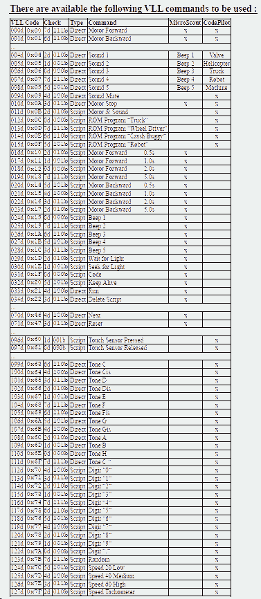
Hello, Reverse-Engineering of this Interface you can find on Youtube The Spybot uses not IR-Puls like RCX but a RS232--to-(visual)-Light Interface. There is Read and Write possible (4800Bd, 8-Data, Odd Parity, 1 Stop) VLL Output is above serial-Interface There is also a IR-Remote (76kHz 25% Duty) to can control the Spybot (same IR-Protocol as Bionicla-Mana, RC-Train and "Nitro-Flash") Unfortunately there is very less information available for Spybots (like available Memory-Size for Commands, used uC, Serial Protocoll and used Commands [possibly sub-set of RCX]) So if you want to extend supported PBricks (Programmable-Brick) please feel free ... By the way, the USB IR-Tower support IR for RCX & Co like also VLL Jo
-
Hello. I'm aware of (see png), Jo
-
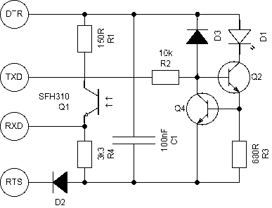
Hello Why not use same Methode used for Spybotic : And yes, you need also an TTL/RS232 Level-Translator like the good old MAX232 or compatible .. Jo
-
Hello, brown-red-red 12 00 -> 1k2 100% identified Thanks, Jo
-
Hello, C5 ? Maybe you mean C8, that in above schematic changed to C1 You wrote also 1k2, but in above Schematic R2 is now 2k2 2k2 would be color-code red-red-red or red-red-black-brown. In Photo of assembled PCB Top-side beside the 2 TO92 Transisors there is no red-red encoded resistor. 1k2 would be brown-red-red (or brown-red-black-brown), but I could also not identify this resistor on Photo. Color identification by photo is difficult What value is correct (Resistor placed at middle Pin of TO92) ? Jo
-
Hello, Are you willing to share the schematic diagram ? What uC and what H-Bridge Driver is used ? Jo