

DanNeely
-
Posts
75 -
Joined
-
Last visited
Content Type
Profiles
Forums
Gallery
Everything posted by DanNeely
-
I've found diagrams for the LH2/LOX piping in the tower itself. Trip Niven is building an extremely detailed model of both the LUT and the surrounding launch complex. He pointed me to the Yahoo Groups LUT_Group, and the extensive collection of engineering drawings that someone had compiled there. Sometime after I'd given up on the group, assuming it completely dead, my request to join was approved. The diagrams there do include ones clearly showing the LH2/LOX piping in the tower. I'm not sure if equivalent detail is available for the ECS piping, but as I linked above I've found images good enough to work that out if need be. I haven't done much on the actual tower the last 2 days, I have come up with a slightly less tortured setup for the ladders to the tower roof/crane though by using a different sort of hinge.
-
It wasn't all doom and gloom today though. I redid the exterior piping using the affordable coupler, painted the bottom of the trusses white, and then went through adjusting out rare/overpriced bricks. With the fences and box trusses (I ordered both of them last month) removed, bricklink priced the remainder of the model at $430 (plus probably $100 in shipping - most parts were from the wrong side of the Atlantic); to that I can probably knock $3-60 or so off because I ordered most of the old A-frame bricks and some assorted ones from higher up to pad out my rare parts orders. Not cheap, but the cost hasn't completely gotten out of hand either, so I'm fairly happy. Still TODO: 1) The platform walls (waiting to see how exactly eiffleman did them for his space shuttle launch platform) 2) Find a way to fit the gearing to connect the two sets of control arms that's out of the way. 3) piping from the sides of the tower to the arms 4) Piping on the arms, along with tweaking their appearance slightly. Probably not to the same level of detail as NathanR's design, partly because the box trusses leave me less freedom to route piping, and partly because I find some of the more tortured construction needed to match the convoluted piping designs rather ugly and am willing to sacrifice realism for aesthetics. 4.5) Access walkways to the arms. 5) Make the crane functional. 5.5) Final decision on functional elevator, and implementation. 6) Redo the tail masts to be retractable, better adjust the hold downs to fit with the larger 14x14 opening (vs the 12x12 they were designed for). 6.5) Add camera platforms (have design, so just need to insert them). 7) Misc external piping. 8) Misc control boxes. 9) Something to simulate the cable runs? These're roughly ordered in terms of priority, but #1's blocked by a 3rd party, #2's still stuck on being annoying and having frustrated me a week ago. #3 is still semi-blocked due to research limitations. For #9, wedging plates vertically between studs looks like it'd work reasonably well for the upper levels, but the 30 foot gaps at the bottom would need a hypothetical 1x9 tile to fit right. Also there doesn't appear to be a way to wedge the tiles in there using either LDD or stud.io (although I know the digital format supports it since the flag tile from the SV set itself is wedged into place). 7-9 are probably going to be done last just because they're going to be in the way of everything else so much. 5.5 may be forced by what I do with the stairs because my concept using bars would block the shaft for a moving car. Beyond that though, if there aren't going to be cars I can extend the floor plates through the shaft making the floor stronger and reducing the total part count. Conversely, if I do have a working elevator, I'd need to open doors all along the shaft, and build a hoist mechanism into the machine room.
-
Keeping the stair design as it was before but with gray landings turns out not to be an option either. There aren't enough gray 26047's available to do all the stair cases. I played around with a few more variations of my plan C from above, trying an attachment to the 48336 on the bottom, but it needed an extension to the top stairs to have something to hold it in place and is really gappy around the landing. I tried bulking things up to fill in the gap, but the bottom stairs end up really chunky and end up protruding forward an extra stud. That in turn sent me back to an old design that I'd tried and rejected previously, using a bar stuck into the elevator shaft as an anchor for the clips. Having the bar in the way makes a mess of the other stairs though. I'm half tempted to use this but with the stairs installed backwards (with the lower segment against the elevator shaft instead of the upper one) because it'd look a lot better.
-
My late night idea about how to keep the stairs all red didn't work. The brick attaching them at the top needs to only be 1 stud (or 3 studs) long so there's overlap at the point between the two sections of treads to keep it all together. I came up with this as a plan C, it works but is kinda ugly. Baring some last minute inspiration it looks like at a minimum I'm going to have gray landings for the stairs. I'll probably keep the treads red though just for contrast.
-
I took a first pass at the propellant/ECS piping, images are available at the linked gallery. I didn't embed them because of excessive scrolling. https://imgur.com/a/nLu6ecv I'm going to have to redo all of it at least nominally because a pricecheck on bricklink put the 2 high axle couplers (6536b) I was using at an average of $1.65 each in white. I can get the 3 high one (28330) for $0.05 each, but swapping them in will require a moderate amount of rework. Axle colors are all placeholders - will be replaced with whatever's cheapest at the given lengths - as are the 32 long axles at the bottom of the propellant lines, those're pending until I create the sidewalls of the platform and can work out exactly how they connect in. They might also briefly go vertical at the 30 foot platform to facilitate connecting the oxygen pipe that goes off on that level. I also discovered one of the pieces I used in the stairs (26047) isn't available in red. It looks like I can make it work by moving the bar to the stairs instead of the landings where I can use a 2 stud plate, but I'm still annoyed with myself for not verifying that the parts were available before rolling them out on each level.
-
Thanks for posting the LDD, that makes it a lot easier to look at what you've done than trying to find a suitable image on the thread/bricksafe. PS you might be able to get cameras onto the camera platforms using a 60849 and a 32002, not sure though because it works in stud.io but not LDD.
-
The educraft model is useless for what I'm trying to find, and from the 2 images you linked I think you're confused about what I'm after. This picture of the model shows the sort of camera angle I'm looking for in actual photos because it would show the route the pipes take between where they run up the side of the tower and connect to the arms, except that the model doesn't have those segments of pipe in it. http://photobucket.com/gallery/user/EduCraftDiversions/media/cGF0aDpMQVVOQ0ggVU1CSUxJQ0FMIFRPV0VSIDE0NCBTQ0FMRSBLSVQvZSBMVVQgMTBfenBzZHZ3ZTN4Zm0ucG5n/?ref=1 The creator admitted to pure guesswork on the part I'm looking for information on... Looking at all the pictures on kickstarter, it only has the ECS piping (the set of 11 on the side), not the H2/LOX piping (set of 6 on the back, 3 going each way when they reach the platform) within the tower with update #28 listing the latter as still todo. The former I've got good image sources for. I've looked at a number of takeoff videos, none at an angle to show the LOX/H2 piping. The only launch video I've seen at an angle/quality level to clearly show the arms is for Apollo 4. With the exception of the crew arm and #3 which didn't have any piping they all stayed engaged until a few seconds before ignition. The staggered swinging at that point would probably need some form of computer control, which's beyond what I'm interested in trying even if the per arm motors would be small enough to fit. A few seconds of most of them is close enough to simultaneous for me (assuming I'm not overlooking an easy way to stagger their movement from a single control anyway). The Apollo 11 one shows an arm slightly to the side of the main group from a camera looking down from near the top of the tower, that's either the crew service arm, or another one swung slightly past where it'd engage the rocket. Whatever arm that is stays there until very shortly before liftoff, being in place at 34:11 (T-0:09) in the video. 24:49 (T-T10:41) shows an external view with the crew arm not visible folded back to its parking position against the tower. It appears the same 4 minutes later 29:06. At 35:29 (t-0:01) it is clearly visible folded back, from the same camera angle as earlier which has me thinking it was in place until very shortly before lift off in this launch. Apollo 12 actually shows it swinging back, 17 minutes into the video (about T- 5 minutes) For Apollo 13/14, the best I can tell is that the crew arm was retracted at least a minute or two before launch (can't find any footage from earlier). Apollo 15 is interesting in that in the moments before launch it only has 5 arms engaged with the rocket vs the 7 in earlier ones, so NASA was evolving the process over time. Apollo 16 appeared to be the same with the 1st stage disconnected earlier than in prior launches. Apollo 17 was a night launch, and none of the film was good enough to make out which arms were deployed or not at any point. My gearing itself is unchanged from what I posted at the start of the week, I've spent most of it down the rabbit hole hunting for plumbing details. I might take a run at it over the weekend, or I might end up just working on the external piping. If I can't find anything on the details of the LOX/LH2 piping, I'm probably just going to assume the high level schematics from the familiarization pdf I found on save the lut is correct other than having the pipes shown as centered on tower instead of to the side with the arms and that they just run directly forward for the LH2, and the same after entering a box for the LOX lines.
-
In the Saturn V image category on Wikipedia, but not linked to specific articles someone uploaded a number of high resolution scans of photos. The two landing pages I linked to below are the best for showing the side piping's routes (I'm not embedding images, because only the full size 7 megapixel ones really have enough detail to be useful here.), others look useful for when I add in control boxes and deck cargo. I haven't found anything equivalent for the piping on the back of the tower yet. (Nothing at a suitably uplooking angle with enough illumination to see where they went.) https://commons.wikimedia.org/wiki/File:Apollo_10_Roll-out_-_GPN-2000-000960.jpg https://commons.wikimedia.org/wiki/File:Apollo_17_Pre-Launch_-_GPN-2000-000636.jpg
-
I heard back from Bailey Fullarton, he said his could hold unto around the weight of the capsule/escape system, and suggested I strengthen it along it's length and add a counterweight to the rear to make it better balanced. I could probably fit a stack of coins in the back section somewhere to increase its weight.
-
MOC: Lego Ideas - Space Shuttle (Saturn V Scale)
DanNeely replied to KingsKnight's topic in Special LEGO Themes
yeah, going to have to paint those too, That or just do an old school white tank I suppose. -
I was able to give the end of the damper arm a diet, I'm a lot happier with its appearance now. I might be able to get 1 step closer still, not sure if it'll work though. My damper arm's a hair off center with the rocket for some reason and the angle piece on the closer side is conflicting with the escape tower. I haven't been able to get the alignment issue sorted (I suspect it's related to needing to rotate the blocks connecting the arms to the tower by a fraction of a degree to get the spacing right to connect to the blocks on the end), so I'm going to have to test-build to see if the second option actually does work.
-
The other thing I'd been working on today was gearing. I did the math on the gearing I copied from whatsuptoday's model, and the gears were the wrong ratio to move both arms correctly. Using what @pagicence initially created for NathanR (left 3 axles) and then adding one additional pair of equal sized gears to the last one I was able to get a set of gears that should be able to rotate both arms at the correct rates. My 1.0 implementation has a few functional issues. First, all the gears and support bricks are hanging outside the tower instead of within: Second the gears are blocking one of the support columns compromising stability: I'm going to try fixing it by moving the complex assembly to the crew access arm and connecting the change direction/offset gears to the main service arm axle. EDIT: That only helped slightly with reducing the amount of sticky out gearing, but left the support column equally obstructed. I'm going to have to think on this a bit more.
-
While I'm still thinking about the gearing/etc around the machine room I did the damper arm. It's a bit chunky at the S5 end, but I'm not sure how to make it more compact while also being able to hold its position. The hitch and ball pieces were originally intended to make trailer hitches I believe, and that would require the ball to be able to freely rotate in the socket. That in turn means that without additional bracing it'd be an LDD only design because they'd just flop down in real bricks.
-
Is your lever mechanism just a handle on an axle and then some 90* gears to pivot the rotation to the correct direction, or something more involved? Unless the crane is teetering on the edge of popping off under it's own weight, it'd be able to lift some degree of cargo without failing. That said, I'm going to ping a few people I've seen build LUTs and ask how strong the attachment holds.
-
MOC: Lego Ideas - Space Shuttle (Saturn V Scale)
DanNeely replied to KingsKnight's topic in Special LEGO Themes
Yikes! Is the orange 45705 the only rare part whose price is a ticking timebomb? I'm not planning on doing a shuttle until after my LUT's done (so probably fall/winter); but if there're any other problematic parts am willing to snipe them up now before prices explode and I have more painting to do. -
I currently don't have a control wheel hooked up, although I've got part of the gearing that originally drove it in place (there was a 3rd gear in place to the lower right of the other 2). The shaft for it would run into the stairs if I tried running it back. I'm debating extending the axle on the gray gear to attach one inside the deck vs removing it an the black gear and just using the arms as the control. I can't visualize what you're thinking Re moving one of the tan gears. They collectively couple the 2 arms together and would need to be moved around as a unit to remain functional. I also need to track down your thread on the technic board, because I have no idea how the lever you've got is working. The issue with the crane gearing is just that it looks like too much stuff to fit within the size of the actual machine room vs building a box the size of the entire deck to hold it all. One cable reel in the box and one outside might work, with the swing arm setup moved down a level, but for cable routing reasons I think I need the spools to be located as close to the center of the cranes rotation base as possible.
-
Most of what I've been working on the last few days doesn't have much to show off. The big two are that I enlarged the launch opening from 12x12 to 14x14 studs moving the SV one stud closer to the tower, and then reattached and in some cases shortened the current placeholder swing arms to fit again. After that, I fixed the stairs between the 0, 30, and 60 foot platforms. The alignment anomoly shown by the different shapes for the landings suggests that the 60 foot platform should be 1 plate higher. I'm not sure if fixing that's worth the pain that would be involved or not. The other thing I worked on was platform 360 and the machinery room. That was a bit fun to do in that there were stairs both gentler in slope (into the machine room) and steeper than the ones elsewhere. Limitations of space meant I had to build the latter as something close to a ladder and hung them fully from the top. The roof of the machine room is flat because it's ridge is only 1.2 studs up from the edges, far shallower than any of the sloped bricks small enough to fit. I tried just a centered line of tiles one stud higher but didn't like the way it looked. I also did a test-fit of whatsuptoday's gearing to connect the two swing arm axis's. The actual fit is a bit ugly, but the only damage it did was slightly displacing the one hanging cross brace forcing me to shorten it a stud to avoid colliding with the railing. In doing so I realized the alignment I currently have for the arm axle's is one stuff off unless I want to create my own gearing setup (I don't). I used purple tiles to mark out where I'd put the 4x4 macaroni tiles that LDD doesn't have. (Stud.io doesn't have the 1x4 fences so I couldn't just swap tools to take a screenshot there.) Having looked closer at the rest of the gearing, I'm pretty sure the answer to if I can fit gears to either work the crane or raise an elevator car in the machine room is no.
-
I've got folders full of schematics DLed from savethelut.com. The problem's an excess of wealth making it hard to find stuff. About the only thing's I've looked for but not found there in any useful detail is the routing of the pipes to the arms or a complete set of drawings of the holddowns. There's a side profile and some other what I assume detail type drawings of sub-components that I can't actually figure out what are. Best source I've found so far for them is a launch video from a camera aimed at the base of the rocket where it sits on the platform. I couldn't see how/what the holddown/release mechanism was from there though, going to have to see if I can find more detail in other videos later tonight. I am mildly concerned about the a-frame strength - even beyond if I need the technic axles as cross braces. I'm hoping that by building the platforms into the elevator shaft that it can serve as the main load bearing element; but it's definitely going to be something I'll need to test build early on to make sure works. The build I copied the idea from was stable even with the shaft detached from the floors, but had a quartet of giant crane stands (2635) running from the 30 to 80 foot platforms with 2x2 brick columns down to the base. I don't like the look of the technic beams punching holes into the floor. If it's the only way to keep it stable I will, but I'm viewing it as a last resort. Removing one of the roof bricks from each column and sticking a pair of 1x3 plates in at the offsets would make them stronger; but would complicate if not preclude attaching the level 30/60 platforms to them at all.
-
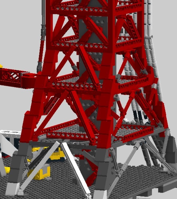
A closeup of the 30 foot platform and various trusses connecting it to the A-frame (with a bit of judicious block hiding). And a few closeup's on the stairs. I'd been trying multiple designs here for a while. 110:1 is really small for this level of detail, but I didn't want to just go with flat ramps. These slotted roof bricks looked great, but working out how to attach them took a while. All the stair segments are only attached at the top. The level going to the bottom deck's supported at the bottom by leaning against the hole in the floor it descends into. The upper level's are supported by a peg going into a technic brick, except for the one in the middle between levels 30 and 60 that's away from the wall and is resting on a clip from the platform. I used technic bricks for the upper part of the elevator shafts to approximate it being made of an open metal lattice instead of solid construction. I thought I was finally done with the stairs last night when I took these pictures, but when reviewing reference images looking for something else saw I was mistaken about how the 0-30 and 30-60 stairs were attached relative to the elevator shaft; and that the rocket facing landing did extend past the edge of the column, so I'll need to redo that later. I'm still undecided on making them red for the color of the rails and risers, or gray to go with the treads. The correction above might make going red more viable since it'd make the spots where the attaching bricks go into the shaft structure less noticable.
-
I've been reading that Japanese model blog you found via Google Translate. Unfortunately that artist wasn't able to find details on how the piping was routed either and just made something up.
-
I've got a few more pictures showing details on the trussing and stairs; but am getting an error now when I try to upload. I'll try uploading them again later.
-
This project's sort of blown up on me. At the start of the month, I was intending to only make a few minor tweaks to an existing design before building it. But one change became two, which became 4... and at this point I've redone most of the tower's structure and am planning to make modifications to most of what's left before I finish. This's where my initially intended tinkering expanded into a top to bottom effort. I've got all the multi-directional cross braces that went here in place, although the hinge based ones are only connected on on end each. I'm still debating what I want to do with the remaining axle based cross beams. Visual consistency suggests changing them out as well similar to what I did for the ones above. The main counter argument is that by being connected top and bottom they're adding a good bit to the structural strength. I might hold off judgment here until I have a test build of the a-frame portion and can see how stable the elevator shaft and main legs are on their own.
-
MOC: Lego Ideas - Space Shuttle (Saturn V Scale)
DanNeely replied to KingsKnight's topic in Special LEGO Themes
Everyone except my wallet thanks you for posting those instructions. :D -
Thank you for those pointers. The supply situation isn't quite as dire as that. There're 2 dozen sellers with at least 25 of them for $0.20 or under, and 19 more with 20-25. It'd be a bunch of orders instead of a one stop shop; but for as many bricks as a LUT needs not an unreasonable number overall. It's mostly a moot point in my case. I was originally planning to build the design I got (Bailey Fullerson's) with only minimal changes from the original design because I didn't want to spent 50-100 hours trying to rework whatsuptoday's into something that had all the needed parts buyable at all. Based on my original plan, I ordered all of the 1x1x4 fences and other rare parts (along with enough misc additional ones to pad the orders out to reasonable sizes to avoid getting crushed by shipping) a week and a half ago. Since then I've probably put 40-70 hours in LDD split about 50/50 between redesigning everything from the taper down and trying to get a smaller footprint for the rest of it that was buildable. *oooops* Assuming I go with it, I'll probably end up spending most of this week redoing the arm and pipe attachments. And then have to either build a partial S-V in LDD to check that the arms still fit, or do a partial physical build to check the same. ('m leaning toward building as far as the first arm, from that I should know how much the others would need scaled.) Currently a solid shaft of bricks. Opening it up to fit a single car's a possible option (the actual pair of cars is probably impossible), but if I do so, that's going to be a fairly late addition. I want to cut the elevator machinery box down to its actual size which'd limit the amount of volume available for gearing, so I'm not sure what'd actually be doable yet.
-
Could you link to where you found the pipe routing and details of the service boxes? I've been unable to find good information on them. I don't know if it'd be enough to let you fit rails with all the other dodads you've got attached, but using 3839's to hang the crossbeams from the level above would cut down a lot on the clutter you'd need to build around. It's what I'm using in my current concept for the main tower levels: