

Ludo
-
Posts
94 -
Joined
-
Last visited
Content Type
Profiles
Forums
Gallery
Everything posted by Ludo
-
@coaster, Great point! Also nice to see the angled in- and out's of the guard rails. A lot more realistic.
-
Thanks both for this information. Next time I'll place bearings into Technic bricks, I'll press them into the brick. Unfortunately, not every Technic piece will withstand the extra pressure. Can't find the picture now, but I've seen a picture with a cracked 18677 plate 1x2 with offset peghole on underside, due to the extra pressure of the bearing. update: found the picture of the cracked plate. https://www.flickr.com/photos/162569845@N05/48568121336/ see:
-
@ALCO The 'problem' i'll noticed is that some bearings dont fit the axle while others do fit on the same axle, So I guess it has to do with the inner diameter of the bearing, perhaps little deformation or a blurr. Putting the axle in a drilling machine or lathe, and use some sandpaper or Schotch Brite to polish will solve the problem. Provided now 4 LEGO wheel holders with ball bearings. Due to the fact I can still use a milling machine, I removed 1mm from the 4 supports. This means that the bearings are 1mm deeper into the wheel holder, and the outher diameter of the bearing makes now one plane with the long sides where the bearings are fitted. This 'trick' ensures that the height of the wagon with or without bearings is the same. To be sure i'll don't loose them, i'll used a drop of hard PVC glue.
-
Hi, I know, I'm late on this toppic, but my ball bearings arrived today, so I will give it a try. I have some mechanical background, and was thinking to use a 5mm HSS reamer to enlarge the Technic hole. @coaster see picture: HSS reamer for those who don't know what it is. It's not cheap, I can use one from my company. I can also use a milling machine to cut a part of the supports on the original wheel holder, as you can see in this picture. https://www.flickr.com/photos/162569845@N05/25210157997 then i can place the axle deeper into the wheel holder to reduce the added height due to the ball bearing at a minimum. Cross my fingers and hope it works. I noticed also a difference in bore diameter, some axles fit perfect on the bearing, others do not fit. I'm almost convinced that this 'problem' is on the bearing side, not on the axle. I guess that the used axles are of the type G7/h6 according to the ISO fitting system (loose fit). the mating hole need to be a H7/g6 Loose fit: combination of axis and a hole, whereby the largest possible axis (according to the given tolerance of that axis) will always fit into the smallest possible hole (according to the given tolerance of that hole)
-
@coaster I can't follow your calculation here above (D=(R x 2 + 1) x 8mm / 25.4mm/in). Could it be you made a mistake in the used numbers (+1 ?) Example: R40 curve is the diameter from the circle center point to the center of the track. To get the outside edge of the curves you need to add 4 studs (from center track to the outer edge of the sleepers) = R+4. Adding an extra 4 studs for the space between the sleepers edge & the edge of the module(MILS or whatever) result for a R40 curve in: R= 40+4+4 = 48 studs (= gray baseplate) Full diameter result in 30,23622 Inch or 2,519685 Feet. My calculation for a R168 inclusive the space needed for the sleepers result in 108,3465 Inch or 9,028871 Feet (R = 168 + 4 = 172 studs) Adding the extra 4 studs space between the sleepers and the outher edge of the module result in 110,8661 Inch or 9,238845 Feet R = 168 + 4 + 4 = 176 studs. D = R x 2 = 352 studs in metric: 352 studs * 8mm = 2816mm or 2,816m in Imperial : (2816/25,4)/12 = 9,238845 Feet. Or am I wrong?
-
Well, here are some calculations of the different R's. A R104 = 32.75591 Inch. I hope that the calculating to Feet is right. (Inches / 12 Being European and use only the Metric system, i'm not familiar with the US dimensions. Way too complicated for me. R 1 stud (= mm) 1 Meter(= 1000mm) Diameter (= R*2) 1 inch (= mm) Feet ( = Inch/12) Diameter (= R*2) 8 1000 2 25,4 12 2 = mm = meter = meter = Inch = Feet = Feet 40 320 0,32 0,64 12,5984252 1,049868766 2,099737533 56 448 0,448 0,896 17,63779528 1,469816273 2,939632546 72 576 0,576 1,152 22,67716535 1,88976378 3,779527559 88 704 0,704 1,408 27,71653543 2,309711286 4,619422572 104 832 0,832 1,664 32,75590551 2,729658793 5,459317585 120 960 0,96 1,92 37,79527559 3,149606299 6,299212598 136 1088 1,088 2,176 42,83464567 3,569553806 7,139107612 152 1216 1,216 2,432 47,87401575 3,989501312 7,979002625 168 1344 1,344 2,688 52,91338583 4,409448819 8,818897638
-
@Coaster, I would rather say disadvanage of 3D printing, as this is much cheaper to make and faster done than coughing up the cost of an expensive mold. Sorry to read this too. Then it easy to understand that you don't share a lot of information. Keep up the good work, still wondering what's coming up. Best regards from Belgium.
-

Vehicle Dynamics Laboratory investigates the Castering Effect
Ludo replied to Hod Carrier's topic in LEGO Train Tech
@Hod Carrier, Thanks for this information. Those bands are indeed cheap and my package contains 200 black bands, so you can do a lot with one package. I used some of them on my wagons to center the single axle wheels back when it exits the curved track. One band for each axle. So far no problems, but i don't attend every wheek an exibiton, so time will tell if I need to remove them. -
@CSW652, I think the mold is too small for the crossover. my guess it's the mold for the missing curved tracks, R72 & R88.
-
@coaster As we see once more a 'new' system from LEGO, i would defenately leave the path of using the 9V connectors. 9v used 2 wire PF used 4 wires Powered up use 6 wires following system use perhaps 8 wires, then we can use UTP or telephone cabling. Guess this kind of connector is worldwide available and cheap too: and the male connector like (90° pins & straight pins - pitch = 1/10 inch = 2.54mm):
-
Glad to read that's not dead. Don't rob liquor stores, when they catch you there won't be 9v or PF tracks. I can imagine that you don't have a lot of time for it, but how's the status of the 9V track? Problem solved?
-
@coaster I found following message in my mail box regarding the kickstarter project for the R104 points : whats next? Ludo
-
Hi @coaster, Just backed for 2 left & 2 right points. I hope it will be funded as there's still a lot to go. I wish you a lot of success. Regards from Belgium. Ludo
-
@coaster keep in mind, that people running with DCC need to bridge the contact in the switch arm. I think its better to make it possible to open the bottom plate to bridge the contact, and re close it on en easy way. Melting pins like the LEGO switches is not the best solution. Perhaps using small screws instead of the plastic pins to melt? It's just an idea you know, but I've seen already - very few - people running their LEGO trains with DCC on a 9V track. Best regards, Ludo
-
Hi @coaster.. Thanks for this update. one question: the kickstarter project for the switches, are they for PF trains only or also prepared for 9V use? I guess, with the high cost of a mold that this mold would be used for PF track as well as for 9v track, or am I wrong? just thinking that the mold could have a metal inlay for molding the 9V version (where the metal track would be inserted), and when removing this inlay, you fill the gap with ABS and become a 100% PF track. I know nothing abouth molds and the possibilities to make them 'universal' so from there my question. b.t.w. I've met yesterday someneone on a LEGO event here in Belgium and he's - as all the reviews i've read so far - also very positive abouth the quality of the PF curved tracks. Keep up the good work. Ludo
-
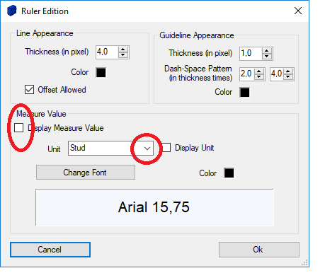
Hi antp You can use marks in meter. Add a ruler layer. draw your line by selecting: Edit | Ruler Tool | Add Ruler once done, double click on the line you just drawed. The Ruler Edition window opens up and you can in the 'Measure Value' frame select the unit you want to use. you have a chooise between: Stud LDU Straight track Module Meter Feet you can use the rules also for a "wall", just deselect the 'Display Measure Value' in the 'Measure Value' frame see the uploaded image. p.s.: will you visit the Brick Mania Wetteren event next weekend? i'll be there as exhibitor and volunteer. Best regards, Ludo
-
Hi Alban, Also, once again a thank you for the support and the verry good communication regarding the 'bug' and the implementation of the MILS connection points. it's a pleasure to 'work' with you. Once i'm done with the final review of the MILSMultiRoad pictures & XML files (Generic City & Generic Terrain = 196 files), i'll send them to Michael Gale to publish them on L-Gauge.org Then it's up to Michael to publish them when it suits him. Ludo
-
Hi Alban, Thanks a lot for your fast reply on my question. Just did a quick test, and made a few minor changes. I'll contacted Michael Gale to see if there are still some changes to be made and keep in touch through e-mail. Best regards, Cordialement, Ludo
-
@Alban Nanty, As you might know, some people and more and more LUG's are using MILS modules. Is there a way that you can implement a few new connection point definitions (0 = .., 1 = ..., 2 = ... , 10 = MILS Terrain,11 = MILS City, 12 = MILS Track, 13 = MILS Airport ) for those modules? I'm thinking on Terrain modules, City modules, Airfield runway modules and train modules. I created almost 100 different xml files for the different combinations of the MILS MultiRoad Modules from Michael Gale, see: http://l-gauge.org/wiki/index.php/Reference_Instructions and used the existing definitions for Road modules. If you can define them, and implement them in the next update from BlueBrick, does this mean that those connectionpoints will be generic for everyone using BlueBrick worldwide. If not, it could generate problems when sharing files among LUG's working on a common MILS project. Those XML files are intend to go public on L-Gauge.org, no release data known yet, as this is totaly in the hands of Michael Gale. So IF you can do this, i'm going to update the XML files with the 'official BlueBrick' connection points. Defining the connection point colors leave I up to you as you know best whats already in use. Hopefully I explained it in a way you understand what I mean.
-
Vehicle Dynamics Laboratory investigates the Castering Effect
Ludo replied to Hod Carrier's topic in LEGO Train Tech
I know it's a pain in the ... to get it working, specially on R40 radii, and most of us have more than a Curver box full of them. I was wondering how the linked cars will behave on larger radii. Would the problem persist, or should it behave better due to the larger radii? I expect they would behave better when pushed. And how would they pass the R104 point from BrickTracks? see discussion on Eurobricks: see: Anyone who tried this yet? -
Vehicle Dynamics Laboratory investigates the Castering Effect
Ludo replied to Hod Carrier's topic in LEGO Train Tech
@Hod Carrier Thanks for this clarification. -
Vehicle Dynamics Laboratory investigates the Castering Effect
Ludo replied to Hod Carrier's topic in LEGO Train Tech
@Hod Carrier Meaning you will keep the link between the 2 Van axles, and add a 'regular' wagon at the end? -
@LEGO Train 12 Volts Well, as you can see, my Medium Azure hopper is a exact copy of the green/gray British hopper. To make it look like the Millet hopper, i need to make some changes. Think I will do it, then i'll have 2 different types of hoppers. I need to be honest and say i'll bought the building instructions from Michael Gale, so i could see how more advanced train builders make their 7 wide wagons. I have no experience in building 7 wide. Anyhow, the green/gray hopper, with its 610 gram is a heavy weight wagon, the VDA Van weights 432 gram. And as last item, take care with the Medium Azure bricks and strong light like sunlight. They tend to change color and become greenish.
-
Well, if you want to add some UK wagons, take a look at Michael Gale's site. see: http://www.brickdimensions.com/store/ and scroll down. I've build me 2 VDA vans, 2 British Rail JIA Hopper wagon and 6 OBA wagons, 2 for each color scheme. No stickers added, yet. And they would fit very nice with this VGA van. See picture below for those British wagons. and here's a picture of the same hopper in Medium Azure, color based on a picture i've found from the French company Millet.
-
Glad to read it.