
DrJB
-
Posts
3,006 -
Joined
-
Last visited
Content Type
Profiles
Forums
Gallery
Everything posted by DrJB
-
 Thank you Jesse, I'll try it tonight and get back to you. Appreciate all the help.
 -
Very easy ... reply, then 'attach/upload/post'.
-
Learning is a slow process ... as it takes us all some time before we 'converge' onto an optimal solution. Some are in it for the fun, others for the sheer joy of helping/sharing, yet fewer others for a business opportunity ... just take what works for you.
-
Yes, that looks right. You can just insert small/tiny pieces of aluminum foil in between the two connectors. Make sure the aluminum foil is small enough so you do not short any other connections.
-
It's VERY easy ... you need the following (all are standard Lego items): - old 9V battery box - adapter cable (from 9V to PF connectors) Now, with above setting, you can power any PF motor (or light) directly (you can also ise a switch/polarity inverter). If you want to use a remote receiver in between, there is one additional detail: The 9V powering the motors/lamps are fed through the inner two wires of the PF connector. The outer 2 wires are for powering the PF remote receiver. To energize the receiver, you need to provide power to the outer wires. This can be easily done by connecting wires 1/3 together, and wires 2/4 together. To do this, you need to inseert small pieces of aluminum foil in between 2 PF connectors.
-
Dacta Control Lab Software
DrJB replied to Dazmundo's topic in LEGO Technic, Mindstorms, Model Team and Scale Modeling
Sorry to revive an old thread but ... has anyone succeeded in running software for 9751 on Windows 7 (64-Bit) ? -
Still have not been able to run InterfaceB ... :( I think I know what the issue is though. The Robolab software (default installation) seems to want to talk to an RCX via a serial tower, not InterfaceB. Thus the question: How do you 'force/configure' Robolab to 'expect' interface B at the end of the serial port ... and not an IR serial tower?
-
Looks promising, though, can you post an LXF/LDD ? ... rather difficult to guess the construction.
-
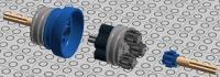
Free Wheel and Flex Coupler
DrJB replied to DrJB's topic in LEGO Technic, Mindstorms, Model Team and Scale Modeling
For the free-wheel, the input shaft is the one on the right (the one with the 8t gear). For the flex coupler (not shown, only in LXF file), it does not matter, as each shaft can be either input/output as the assembly is symmetric. Sorry can't post a pic of the flex coupler as running low on posting allocation. -
Not to revive an old thread but ... just got this off eBay, it's a nice studded model.
-
Free Wheel and Flex Coupler
DrJB replied to DrJB's topic in LEGO Technic, Mindstorms, Model Team and Scale Modeling
A centrifugal coupler and a free wheel are NOT the same thing ... A centrifugal coupler engages when the rpm reaches a certain value ... A freewheel engages in only one direction, no matter how small or large the rpm is. -
Free Wheel and Flex Coupler
DrJB replied to DrJB's topic in LEGO Technic, Mindstorms, Model Team and Scale Modeling
FreeWheels and Flexible Couplers are often used in off-highway and industrial applications. I did not imply they must be used on your typical lego cars, but nonetheless. those are rather wide-spread mechanisms. A free-wheel transmits rotation in only one direction (and there is one in your bicycle). Try and build it, and you'll see that the input/output shafts (axles) rotate together only in one direction. If you reverse the direction, the connection is lost. As for the flex coupler, typical internal combustion engines do not run at constant RPM. There is torsional oscillation/vibration superimposed onto the average RPM. A flex-coupler is typically used to absorb/reduce such oscillations. You will not see such oscillations with any of the Lego PF motors. Lastly, my interest in Lego is not to build nice looking cars ... I'm in it primarily to reproduce real-life mechanisms, and the freewheel and flex-coupler do exist in real life. Not quite, it seems you missed the point about the use of 8t gears (in my specific contraption). From what I can guess from your picture, your design is essentially a flex coupler as the rubber elements are connect on both sides. In my design however, the gears make the rubber parts rotate and push harder against the contact surface, to increase the grip. The harder you twist, the higher the friction, and the higher the torque you can transmit. It is VERY different from your design. Also, my design transmits zero torque/motion in the opposite direction, and that is why I called it 'freewheel'. Check out the site below to understand how a freewheel works http://en.wikipedia.org/wiki/Freewheel -
Your Best Technic Bargains
DrJB replied to Kumbbl's topic in LEGO Technic, Mindstorms, Model Team and Scale Modeling
If I recall, the first 100 entries got a free 41999 .... Or something like that. -
Free Wheel and Flex Coupler
DrJB replied to DrJB's topic in LEGO Technic, Mindstorms, Model Team and Scale Modeling
145 views ... 17 downloads .. and not a single answer? Sorry guys, despite the thread title ... this is NOT about giving away FREE parts ... lol -
[HELP] Live Axle Geometry
DrJB replied to piterx's topic in LEGO Technic, Mindstorms, Model Team and Scale Modeling
Rather surprising ... I need to look under my Odyssey and my neighbor's Sienna ... -
Two designs I thought up ... 1. A free wheel transmits rotation only in one direction, and is free to spin in the opposite direction. 2. A flex-coupling is well ... meant to absorb misalignments and quench torsional vibrations Both designs are rather sturdy (for rigidity) and may be simplified. FrWheel and FlexCoupler.lxf
-
I just got the GoPro Hero 3+ and it has 'too much' fish-eye. From my recollection, the 3 (not +) has a bit of a narrower FOV, and thus less distortion. Looking into add-on lenses to counter the fish-eye but have not found any yet.
-
Check out some of the videos Mahjqa made for his metal grudge. He built a small vehicle, that holds the camera, and moves at the same level as the subject/target vehicle. www.vayamenda.com
-
[HELP] Live Axle Geometry
DrJB replied to piterx's topic in LEGO Technic, Mindstorms, Model Team and Scale Modeling
The last time I worked on car suspensions ... I recall that the leaf-spring is a thing of the past ... inherited from horse carriages. True, Ford had them on their Explorer Sport-Track up until 10 years ago (Colleagues and I were pondering what was Ford thinking ...). But then again, ABS did not become a standard feature until 10-15 years ago in the US. Also, when you stagger multiple leafs of various lengths, you get a non-linear/progressive stiffness (which is desirable in many instances), but that was oh-so-last-century, with an understanding of vehicle dynamics I'd qualify of rather primitive ... We have come a long way since those. -
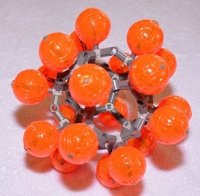
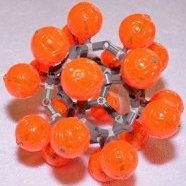
Efferman's Custom Parts
DrJB replied to efferman's topic in LEGO Technic, Mindstorms, Model Team and Scale Modeling
Very nice ... now need a volunteer to design the heptagon (7 sides) structure that'll support all of this. -
[HELP] Gear Reduction Ratio
DrJB replied to Lego Otaku's topic in LEGO Technic, Mindstorms, Model Team and Scale Modeling
much much better ... I was wondering what that series of numbers meant ... You can go back, edit your post, and modify it. No need to repost. -
[HELP] Lego Aerial Tramway
DrJB replied to elx's topic in LEGO Technic, Mindstorms, Model Team and Scale Modeling
From what I have seen, the cabins typically do not travel on the wires .... They are instead attached (via a clamping mechanism) to the wires, and the wires move. Also, making the cabins move on the cable means you need to motorize each one of them ... Check this thread http://www.eurobricks.com/forum/index.php?showtopic=91533 -
[HELP] Live Axle Geometry
DrJB replied to piterx's topic in LEGO Technic, Mindstorms, Model Team and Scale Modeling
somehow the picture does not show ... -
EV3 Holonomic Robot
DrJB replied to Aswin's topic in LEGO Technic, Mindstorms, Model Team and Scale Modeling
Thank you Aswin and EV3Noob ... promising to be a lot of fun, will most likely do this on spring break (in 3 weeks) ... working adult life does not go hand in hand with such a dedicated hobby ... will update then. -
Motorized Crane Platforms
DrJB replied to DrJB's topic in LEGO Technic, Mindstorms, Model Team and Scale Modeling
You do not need another motor, one function is already 'wasted' on the super-structure as you need the red lever to be in the bottom left position to activate the outriggers (send power to the chassis) and then another switch that control up/down or in/out of outriggers. You can instead have power running continuously to the chassis, and that's how you recover one function on the superstructure. What you do need though is an XL motor as the L barely cuts it. The gear trains have a lot of friction in them as they're optimized for 'compactness/symmetry', not necessarily for friction losses. Granted, maybe it makes no sense as the machine is NOT RC operated ... but still.
