

Dzmitry
-
Posts
15 -
Joined
-
Last visited
About Dzmitry

-
Barrier Transfer Machine
Dzmitry replied to Dzmitry's topic in LEGO Technic, Mindstorms, Model Team and Scale Modeling
Part 4: Frame and Motors After a short break, I finally got back to the project. I started by running the barriers back and forth through the grabber system a couple of times and decided to add another grabber section in the middle. That also helped solve the even/odd length issue between the chassis and the grabbers. Next, I reworked both chassis sections and adjusted the mounting height for the grabbers. The main load-bearing structure consists of two pairs of trusses and a turntable in the middle. Once it was all assembled, I realized that the whole vehicle essentially functions like a gantry crane. That insight helped me understand something crucial: since I’m building such a specific type of crane, the grabber-supporting truss should be positioned directly above the wheel axles, so the weight is transferred straight down. Otherwise, the whole thing starts to sag and look like a badly pitched tent. If you look at the build from above, the grabber layout resembles the graph of y = –x³, with open space in the first and third quadrants—perfect spots for placing the drive motors. Yeah, time to flex that high school math knowledge a bit. Guess it finally came in handy! 😄 So, after placing the drive motors and the battery box, I started figuring out how to route the axles between the wheels. Using a few gears, I “climbed” above the grabber line, and the resulting axle system turned into a zig-zag, with two 90-degree changes in direction—and everything's now properly connected. For steering, I decided to use a worm gear combined with a distribution gearbox featuring a switchable drive. But this is where the zig-zag axle layout caused major headaches. Every pair of meshing gears adds backlash, which results in steering delays. An even bigger mistake was using a driving ring (clutch)—it only has four engagement points, meaning a quarter-turn of the axle produces no output. One way to compensate is to increase the gear ratio, so that a 1/4 turn has a smaller effect on the system, but this still doesn't solve the problem of asynchronous wheel steering, and therefore asynchronous grabber alignment. So the entire steering system needs to be redesigned. For the vehicle to maneuver properly, the second axle must have a mechanism to switch its steering function on and off. At the end, I’ll include a video to give a better idea of what the current setup looks like. I haven’t yet added the drive system for the moving grabbers—I only marked the axle positions. Functionally, this system will be similar to axle drive, but the challenge lies in stacking all three subsystems vertically: Drive / Steering/ Grabbers. Another issue is that I’ll either need to install a second battery box to power and control the grabbers independently, or use a driving ring (clutch mechanism) to connect the grabber drives to the wheel drive system. That approach actually makes sense, since the grabbers only need to push the barriers when the vehicle is moving forward. I forgot to take photos during the building process, so if anyone’s interested, I can take some when I disassemble the machine to rework the steering system. The further I get into the build, the more I realize that this is way more complex than I originally thought. The machine is effectively split diagonally, and that affects everything—balance, sagging, and drivetrain routing. The sagging isn’t just along the longitudinal axis, but also noticeable across the lateral direction. If one side is overloaded, the machine starts to flex, because the wheel support points aren't aligned with the full width of the build. In several places I added CV joints to prevent the axles from binding in the middle of the structure. -
Barrier Transfer Machine
Dzmitry replied to Dzmitry's topic in LEGO Technic, Mindstorms, Model Team and Scale Modeling
That's cheating -
Barrier Transfer Machine
Dzmitry replied to Dzmitry's topic in LEGO Technic, Mindstorms, Model Team and Scale Modeling
Part 3: Test Stand I started the evening by reworking the steering system and drivetrain. I optimized the number of parts and reinforced the structure to ensure the necessary rigidity. Next, I assembled a small section of the body to get a better sense of the vehicle’s overall height proportions. Based on this, I’m considering abandoning the linkage system and instead controlling both axles’ steering through gears and axles. At this point, there was no way around it—I had to figure out the barrier-pushing mechanism. In the real-life machine, it looks like each grabber wheel has its own drive, essentially functioning as a conveyor belt. I decided to simplify the system and use two separate drives for the moving parts of the grabbers: The front grabber will pull barriers into the machine. The rear grabber will push them out the back. I was concerned that friction would be too high, causing the rubber wheels to slip uselessly. To address this, I deliberately designed all moving sections with slight flexibility, since the barrier "snake" can bend, meaning the mechanism needs to adapt dynamically. As seen in the photos, the grabbers have grown significantly in size. Now, I need to consider how to prevent them from sagging under their own weight. The most challenging part was figuring out how to spring-load the axles with the wheels so that they would press firmly against the barrier. I spent a long time experimenting with different ways to attach a rubber band to each axle, but every setup ended up being too bulky. Then, I remembered a simple rope trick—a way to connect two ropes without actually tying them together. As it turns out, the simplest solution was also the most effective. In the final version, the rubber bands pull the moving axles toward each other. There’s no risk of the rubber bands wearing out, as they are separated from the rotating axles by 2L hollow tubes. After assembling the moving grabber mechanism with powered wheels, it was time to quickly set up a test stand and see if the system could actually move the barriers. In the highlighted area of the photo, you can clearly see that the barriers are being lifted off the ground and repositioned, rather than just being dragged along. This means the mechanism is functional! Even if moving the entire barrier "snake" with just two powered grabbers turns out to be too difficult, the problem will then be purely quantitative—I’ll just need to add more units and buy additional wheels and rubber bands. From a qualitative standpoint, the problem is solved! And as seen in the video, I might have to redesign the barriers. The spacing between the segments is causing issues—either the barrier gets stuck in the mechanism or the wheels slip into the gaps instead of maintaining grip. Now, I need to rethink the barrier design to ensure smoother movement through the grabbers while maintaining flexibility. -
Barrier Transfer Machine
Dzmitry replied to Dzmitry's topic in LEGO Technic, Mindstorms, Model Team and Scale Modeling
I have two standard Power Functions battery boxes. Today, I ran into the issue that I’ll need to buy additional parts. Even in the best-case scenario, I’ll still need: Four standard rubber bands Four wheels (like the ones in the photo) I thought I had everything, but it turns out I only have three of each. -
Barrier Transfer Machine
Dzmitry replied to Dzmitry's topic in LEGO Technic, Mindstorms, Model Team and Scale Modeling
I have a total of five motors power functions in my collection: three L-motors, one M-motor, and one servo motor :( -
Barrier Transfer Machine
Dzmitry replied to Dzmitry's topic in LEGO Technic, Mindstorms, Model Team and Scale Modeling
I plan to use two L-motors for driving and one motor for steering. A servo motor won’t work in this setup since I don’t need the wheels to automatically return to their original position. Additionally, I want to include a switching gearbox, allowing me to connect or disconnect the rear axle from the steering system. Right now, I haven’t figured out a working mechanism for pushing the barriers forward, but if I manage to design one, it will require an additional motor. -
Barrier Transfer Machine
Dzmitry replied to Dzmitry's topic in LEGO Technic, Mindstorms, Model Team and Scale Modeling
Part 2: Prototyping This evening, I started by trying to develop a barrier-pushing mechanism, but nothing seemed to work. So, I decided to first build a chassis model to get a sense of the overall dimensions and the challenges of integrating the grabber mechanism with the chassis. After looking at a few photos of real barrier transfer machines, I noticed that the wheels are not aligned in a straight line. For crab steering mode, a fully steerable chassis is essential. Additionally, to avoid the need for full U-turns, I considered a dual-front design, where both front sections have steerable wheels and motor-driven power. I quickly determined the wheel size, but after positioning them next to the grabbers, I realized there wasn’t enough space for a standard differential. Since I haven’t built many vehicles before, I decided not to jump straight into a final assembly but instead to prototype a test model. This way, I could properly evaluate the wheel turning angles and overall geometry before committing to a final build. There’s still a lot of work ahead to refine the entire mechanism. My main goal is to reduce backlash and improve the responsiveness of the wheels when turning the gear that controls steering. After connecting both halves of the frame side by side, I placed the grabbers on top and immediately noticed that the chassis was too long, so I shortened it. The next issue was that the chassis had an even length, while the grabber assembly had an odd length. To solve this, I built a custom adapter (shown in the middle photo). The barrier grabber system has moving parts on both ends, and they need to operate in such a way that the barriers enter and exit in the same direction regardless of the wheel angle. That’s when I realized that the pivot point of the rotating grabber should align with the wheel axle. This effectively makes it function as a third wheel, ensuring synchronized turning between the wheels and the grabber assembly. It took me three attempts to find the optimal mounting points for the grabber mechanism and the beams that would fix its position relative to the chassis. The main challenge was ensuring the wheels could still turn while keeping the overall width of the construction as narrow as possible. Once that was sorted out, I was able to convert the movable part of the grabber into a "third wheel" for the steering system. After that, I added a beam to enable opposite-wheel steering, allowing the wheels to turn in opposite directions for better maneuverability. Mission accomplished for today: when the wheels turn, the grabbers follow along, which is clearly visible in the photos. Of course, I will need to completely disassemble and rebuild everything, but now I have a clear idea of the vehicle's dimensions and all the critical connection points between the frame and the grabbers. I didn’t focus on vertical proportions yet, so the grabber assembly will need to be adjusted in height to match the barrier's actual height. -
Barrier Transfer Machine
Dzmitry replied to Dzmitry's topic in LEGO Technic, Mindstorms, Model Team and Scale Modeling
I agree, rounded elements are perfect for the barrier build. I checked my parts inventory and I have exactly 0 of them! :) -
Hello everyone! This will be a series of posts about my attempt to build a Barrier Transfer Machine. The model is based on the Road Zipper, a vehicle used to move concrete barriers on roads with reversible lanes. First, I tried to build a flexible barrier made of linked segments. After some thought, I realized that it could resemble one half of a zipper mechanism. The barriers are connected with a 0.5-stud offset between them, allowing for good flexibility while keeping them close together. Selecting the right dimensions for the grabbing mechanism wasn’t too difficult. The optimal angle was achieved using a #4 connector. However, later on, the number of required parts significantly limited my further assembly process. The distance between the grabbers is exactly 3 studs—this is intentional. I designed it so that when the small wheel is positioned between the barrier links, the neighboring grabbers provide support to each barrier. The next challenge was designing the S-shaped guide. The best shape was achieved using two sections of curved gear racks. However, these parts don’t have enough pin holes to mount all the grabbers. One way to replicate their shape was by using angled connectors. To match the curvature precisely, I needed four 3L axles and four #4 connectors. But since I had already used 13 of them for the grabbers, my remaining stock was just 3 pieces, which was far from enough. So, I had to come up with something original! A flexible axle helps adjust the angle of each grabber, while the opposite side of the structure consists of vertical angle limiters. This way, all the grabbers are positioned with an offset both horizontally and vertically. The next step will be fine-tuning the grabber positions using a 1x1 beam on the flexible axle. In the video, it already works quite well, even on the first attempt! To be honest, I’m not sure yet if it will be possible to attach a motor with a wheel in a way that actually pushes the barrier inside. It might just have to be simulated instead. I’d love to hear your thoughts and suggestions! Hopefully, I’ll find enough free time to keep updating this thread regularly.
-
Could you please suggest parts packs from 2022-2025? I love building various vehicles and special machinery in LEGO Technic, but my budget for LEGO is limited, so I often hesitate about what to buy. Right now, I think the best value-for-money parts pack is 42181.
-
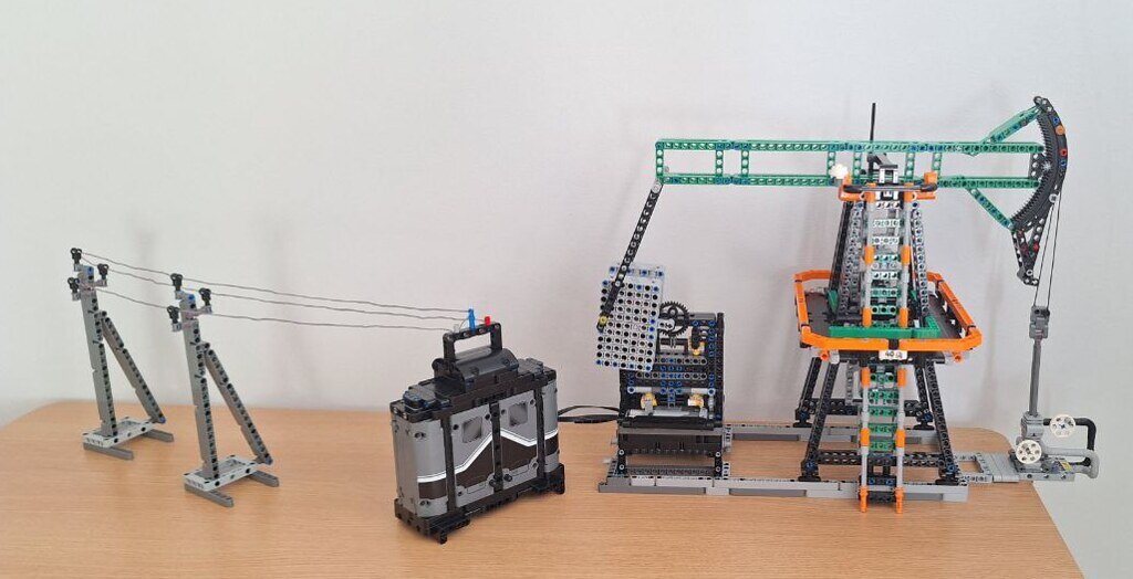
Oil Pumpjack This is my first time participating, and I didn’t notice that I needed to duplicate the application here. Description of the functions: 1. Horsehead, Beam, and Crank-Slider Mechanism: The main element of the structure consists of a beam connected to a horsehead, simulating the rocking motion of a real pumpjack. The crank-slider mechanism converts rotational motion into linear motion, creating smooth and stable oscillations of the beam. 2. Counterweight: The counterweight stabilizes the movement of the entire structure, maintaining uniformity in the beam’s rocking motion, making the mechanism more efficient. 3. Electric Motors(2L): These drive the entire mechanism, automating the rocking movements. 4. Power Supply: The battery pack is placed in the form of a transformer booth, and power lines supply energy to the motors, imitating the real power supply to an oil pumpjack. https://www.eurobricks.com/forum/forums/topic/201535-tc28-oil-pumpjack/
-
After university, I worked as a geophysicist for six years. As a result, my usual work scenery often consisted of oil pump fields. So when I read about a competition for non-transport mechanisms, I didn’t have to think long. The first thing I decided to assemble was the beam and the horse's head. After putting the entire structure together, I had no regrets about how I connected them. I had to spend a long time adjusting the beam's connection angles to effectively convert its rocking motion into the linear movement of the rod. The second part of the assembly was the beam support. I decided to abandon vertical supports and made them inclined toward the beam. Then, I added a maintenance platform and a ladder running along the entire support. The crank-slider mechanism made me spend a lot of time selecting the proper height for the crank attachment point, its length, and the length of the connecting rod to ensure the beam oscillated within the desired range. I didn’t expect the counterweight to have such a significant impact on the uniformity of the entire structure’s movement—it was a real discovery. I quickly added the motors, and the only question left was: where should I place the battery pack? I had long thought that the shape of the battery pack resembled a transformer booth, which inspired the solution—to create a transformer and power line supports to supply energy to the pumpjack. Finally, I put everything together! P.S. I'm translating into English using ChatGPT, so there might be some mistakes :)
-
Thank you very much! Now, please take a look at all the photos 🙂
-
https://bricksafe.com/register/ Sorry, we are no longer accepting new registrations. Existing accounts may still login. As I understand it, any file-sharing service should work, right?
-
Hello everyone, it's my first day on this wonderful forum, and I decided to share my LEGO Technic MOC, which I spent a long time building but eventually abandoned. I want to share some photos with you and take it apart for new ideas. I've had the 42078-1 Mack Anthem set for a long time, but its wheels always seemed too small to me. So, I decided to scale up the truck to fit 62.4 x 20 wheels. The new width is 18 studs at the front and 19 studs at the rear, and the length is approximately 52 studs. I tried to maintain the proportions of the original model, including the cabin interior and the driver's sleeping area. Then I got carried away with redesigning the model, adding suspension to the rear axles and dual wheels. I had to work hard to maintain the longitudinal rigidity of the main frame, especially at the connection point between the cabin and the rear axles. The presence of a floating suspension significantly reduced the possible reinforcement points in the structure. However, in the end, I was quite satisfied with the suspension. I also installed remote control using two L-motors and a servo motor. I placed the battery pack and radio transmitter behind the sleeping area and under the truck's roof. I kept the inline six-cylinder engine under the hood. The trailer turned into a real road train, consisting of two trailers for a single container and one trailer for two containers. I then built two containers from the original set: one shortened version and a special container for transporting gas. I would be very happy to read your feedback, recommendations, and advice!