

tseary
-
Posts
40 -
Joined
-
Last visited
Content Type
Profiles
Forums
Gallery
Everything posted by tseary
-
General Part Discussion
tseary replied to Polo-Freak's topic in LEGO Technic, Mindstorms, Model Team and Scale Modeling
I like the look of those gear tracks as a miniature successor to monorail! Although I hope they come out with a wheeled base as an alternative to the sliding carriage shown here, it's not so suitable for trains of any scale without that. -
This is nice. Last weekend I was inspired by the mild winter weather to build a snow-worthy RC vehicle. While searching for reference material I happened upon @mahjqa's own "Stilzkin Indrik" arctic truck MOC from 15 years ago. I'm currently trying to replicate something like it (using Powered-Up motors instead of PF). It was a cool coincidence to see the old Indrik and this new truck conquering the snow in the same week!
-
General Part Discussion
tseary replied to Polo-Freak's topic in LEGO Technic, Mindstorms, Model Team and Scale Modeling
I agree, but my point is that it wouldn't take an army of printers for a production run like this. Presumably print times don't vary by a huge amount between SLS printers. Personally, I hope that TLG isn't investing too much in 3D-printed production parts. In my opinion they only appeal to the collector market, and don't add play value. -
General Part Discussion
tseary replied to Polo-Freak's topic in LEGO Technic, Mindstorms, Model Team and Scale Modeling
For some very coarse napkin math, the Formlabs Fuse 1+ SLS printer (for example) can print a full job in 14 hours. The build volume is 16.5 x 16.5 x 30 cm. Assuming the little train is 2 x 2 x 4 Lego units, plus some margin, you could fit about 500-700 of them in a job. Running around the clock and ignoring scrap factor, they could print a run of 50,000 parts in a month on just two of these printers. The cost would be well under $1M. That points towards this being a gimmick. -
You make a good point. I didn't know that Buwizz had that feature, I was mainly thinking of the default PF receiver.
-
@gyenesvi So I did assemble a couple of prototypes of the servo adapter. It works as intended, but I'm not totally happy with it because there's no way to trim the center and limit angle of the servo. Adding that feature will probably mean going to a different microcontroller, which is not so bad, but it won't be as compact of course. Before I make another version of the adapter, I have to finish the test car I'm building. Like all hobbies it has to compete for time...
-
[TC29] BullDozer - Finished
tseary replied to MangaNOID's topic in LEGO Technic, Mindstorms, Model Team and Scale Modeling
That steering gear is really cool! I was wondering how to build a skid-steer vehicle with the Technic Control+ hub, which is intended for rack-and-pinion steering. This could be a way to make that work. -
45 Degrees in technic
tseary replied to Alien's topic in LEGO Technic, Mindstorms, Model Team and Scale Modeling
@Stereo That's a good one, it would be useful wherever rigidity is needed. Mine isn't so strong because of the 1L side. I'm tempted to look for other angles of 360/N so I can build a big Ferris wheel or something. -
45 Degrees in technic
tseary replied to Alien's topic in LEGO Technic, Mindstorms, Model Team and Scale Modeling
I'm posting on this old topic because I was nerd-sniped by this challenge today, and I discovered a way to build a perfect 45 degree angle! In the top image, the red link forms the hypotenuse of a triangle with side lengths 1, 3, and 2*sqrt(2). The structure can be doubled up in a tight space for rigidity, as shown in the bottom image. -
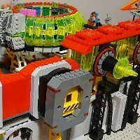
I slightly prefer the black rams, but the white cab looks great. The blade looks a lot better without black parts too.
-
Hybrid Lego car platform
tseary replied to chronologically's topic in LEGO Technic, Mindstorms, Model Team and Scale Modeling
A couple of suggestions: Minimize the number of idle gears that are turning in pullback mode. I think they will sap the power of the pullback motor. You might achieve this by placing the clutch directly on the output axle. Perhaps do away with bevel gears entirely. It will be most efficient to use spur gears for everything. The rectangular frame parts (https://www.bricklink.com/v2/catalog/catalogitem.page?P=39794, https://www.bricklink.com/v2/catalog/catalogitem.page?P=4526, etc.) are good for keeping things square and rigid, if you have some of those. -
Yes and yes. The PF cable is permanently attached, and the servo plugs in. The microcontroller is the smallest one I could find, which has limited resources. The program is small, so writing Assembly is not too much of a burden, although I am using an Arduino Uno as a programming interface. The programming cable is held in place by hand, in the 4-pin connector.
-
Last week I received the new boards for my PF to servo converter. I got the size down to 21 x 10 mm. I still need to write the program, which will be in Assembly.
-
There's so much to notice and appreciate here. The fully tiled boom and cabling looks great. NPU on the wrist straps around the spare tire. And I just noticed the crane operator! I call myself a purist but I'm also guilty of painting on occasion... I'd say it's completely justified for this result.
-
Nice work! The possibility of driving directly with a gamepad is very appealling compared to the Lego remotes, or smartphone. You mentioned there is battery discharge protection. Is that built into the motor driver, or is it implemented in software?
-
Thanks for asking. I've designed a new minimal version without the IR receiver, and only a single servo output. Using the smallest SMT parts I could manage, the board measures just 12x24 mm. But I haven't ordered the parts yet, as I need to finish some other work before digging into this. The new design has a different microcontroller, so it will require fresh code.
-
General Part Discussion
tseary replied to Polo-Freak's topic in LEGO Technic, Mindstorms, Model Team and Scale Modeling
I'm here for the transparent tires! I just picked up the Creator roller skate for the pink tires too. Maybe someone will find a nice way to illuminate the green tires too. -
6 DOF Cube
tseary replied to schraubedrin's topic in LEGO Technic, Mindstorms, Model Team and Scale Modeling
Thank you for sharing this. I had never heard of this mechanism before! It really looks like sci-fi tech; Borg or something... I wonder how this compares to the Stewart platform in force and range of motion. I'm guessing the Stewart platform has some kind of advantage considering how common it is. Although I can imagine this cube being applied in a modular robot. -
@LabManager where did you get the MK servo from? I see MK servos being sold individually on ebay; I'm tempted to get one to experiment with (or dissect) but I'm not sure it's the right kind. As I understand from your first post, the only thing that changes the servo behaviour is frequency. 470 Hz gives +/-90 degrees, and >980 Hz gives proportional control. Did you try even higher frequency beyond 1200 Hz?
-
@gyenesvi Sorry, I didn't add any instructions yet. I'll try to do that during the week. A couple of short answers; the board is reflow soldered using solder paste and hot air. The chip is programmed through the ICSP header - this can be done using an Arduino Uno and the "Arduino as ISP" option.
-
Good idea. I was thinking just 2 holes, but if it were small enough it wouldn't need any. This is a good point. One advantage of servos over PUP motors is that servos know their absolute position.
-
I've made the GitHub repo for my servo controller public, and I also uploaded the KiCad files: https://github.com/tseary/Sergo The existing design is indeed 3x5 studs. With a smaller microcontroller, single servo output and no IR receiver it could probably fit into 3x3. Maybe I'll look into this tomorrow...
-
On the subject of converting C1/C2 to servo PWM without a microcontroller, this is doable... As a rough concept, I would suggest the following: 1. Convert C1/C2 to analog by RC filter. Combine these two signals into one with an opamp subtractor. 2. Generate a PWM for the servo from a 556 timer. (The 556 is two timers. The first produces a constant frequency to trigger the second timer, which is configured as a one-shot). 3. Let the combined analog signal determine the pulse width of the one-shot timer. The result is the servo signal. There are a number of issues with this approach that are solved by a microcontroller. Foremost is that it would take at least double the space - although it could be a few cents cheaper in volume.
-
I've done something similar a few years ago to connect hobby servos to Power Functions. (In the image below, a 2x5 studful Geek servo). This custom PCB has an ATTINY84 microcontroller to read the C1/C2 PWM and drive the servo accordingly. There is also an IR receiver which allows direct control without a Power Functions receiver.
-
Wooooooah! That FPV car is awesome! I was thinking of getting an ESP32-CAM for machine vision stuff but I didn't realize it can stream live video. Long ago there was an online simulator game in which the player controls a Mars rover based on images sent back from the rover. The game had a simulated time delay to represent the transmission time, so you had to program your movements and then see the result. I always thought it would be cool to make a real version where you control a model rover in a different room.