
johncarpenter
-
Posts
55 -
Joined
-
Last visited
Content Type
Profiles
Forums
Gallery
Everything posted by johncarpenter
-
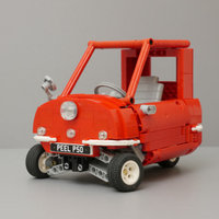
 Hello everyone, I want to introduce my new project: The Linde P250 Tow Tractor: This is only my third project after returning to Lego Technic after 20 years, so I consider myself a beginner as I have little experience with studless building. After my last project (RC skid steer) where I had a lot of headaches fitting everything in, I wanted to build something simpler for my next project. I picked the Linde P250 as the reference for this build. The starting goal was not to have an accurate scale model, but to have a simple remote controlled model that could drive around. The real one has two versions, a short and long wheelbase. I picked the long wheelbase version to have more room for internals. According to the scale I chose, the model was going to end up 13 studs wide, which looked tight but doable. As I only planned to have driving and steering, I thought that this should be fine. After picking some suitable wheels and printing out the blueprint, I started off with the exterior design, sides and front first. I was studying pictures and videos of the real thing and this is where I started to add some things to the original plan. There is a lever in the cabin that locks and unlocks the trailer coupling. Using this, the operator can grab or release trailers without getting out of the cabin and walking around to the back. Also, I saw that this particular model is available with normal or sliding doors, so I wanted to try the sliding of course. Finally, the tractor can be driven (very slowly) forwards or backwards from outside using a pair of buttons, again to make working with trailers easier. I knew that this function was going to be challenging, due to the limited space available at the back of the vehicle. There goes the idea of keeping it simple this time... I started to redesign the sides to have sliding doors. There was a tricky point with the doors: On the real thing, the door has a piece which closes the gap between the bottom of the sliding door, and the cabin floor. If this piece were to be fixed to the door, it would interfere with the front wheel when the door is slid back. Therefore, it swings into the door and disappears when the door is slid open. I had to either make something similar or leave a gap there. My first version of the sliding doors worked, but had two issues: The door slid back only 5 studs, which seemed too little and the swing up piece did not work great. I iterated on this to fix both problems: I replaced the flap thing, and played around with the geometry of how it slides up. Also, I changed the vertical door post and the rail support at the top of the door to be half width linkarms. Now, the door was able to slide 6 studs, and the swing up piece looked good and worked reliably. I did play around with making the door open even wider, but it looked like anything more than 6 studs would mean a lot of other compromises, so I settled on that. I also worked on the front: The first iteration looked way too narrow, so I moved the headlights outward: In parallel, I was looking at how to package the internals. I wanted to use the normal AA battery box, but at 11 studs wide, it was challenging to fit. The most efficient way seemed to be to have it in the middle of the chassis, at the bottom. That way, it fit exactly between the side panels, and even protruded half a stud below the chassis, saving space by cheating slightly. In researching the pieces I would need to build this in red, like the original, I realized that some of the thin liftarms I used on the door were not available in red. The issue if I used normal liftarms was that the door would slide just 5 studs. I redesigned the mechanism, to use a normal liftarm for the vertical part of the door, and used a short liftarm (yellow in the picture below) which was able to slide 1 stud under the roof. This way, the door was able to slide 6 studs, and did not need the thin liftarms. I also redesigned the sides, using 5x11 panels at the bottom, which improved both the looks and the structural stability, especially of the battery box mounting. With the exterior starting to come together nicely, next up was to see if I could fit all the functions inside. I wanted to have an L motor for driving and a servo for the steering. For the "driving slowly using buttons on the side of the vehicle" function, I needed an M motor, a clutch to switch the drive to this motor, some gearing down, and a PF switch. I had selected the scale before deciding to add this feature, and it was looking quite unlikely that everything would fit inside. This is where I am at right now. At this point, I'm thinking that I either need to go from a width of 13 up to 15 studs, or give up on the "button driving" function. I do think that feature adds a lot to this relatively simply model, so I would really like to keep it. Actually, widening by 2 studs has a lot of advantages at this point: Currently, the space available above the battery is exactly 9 studs wide. If I widen to 15, that would give me 11 studs of room in the top half, which means I can move the battery to the top. This would then free up 13 studs of width below, for the motors etc... As I still don't have a front axle, I think I will build that first with the servo. Based on that, I can see exactly how much space I have left and then decide if I will widen the model.
 -
I guess this would work, however, I don't have an extension cable or a second switch to try it with. Anyway, thanks everyone for the help, but it sounds like this is not so easy. I think I'm going back to my original plan of putting another M motor in there. The functionality will be the same and it will be simpler than having two switches.
-
It is not just about reversing the direction. I want to have the same motor driven by remote control, but also by a switch on the vehicle itself. I'll post the project soon, to explain how this is supposed to work. Thanks, I guess I'll try it tomorrow and report back. I hope nothing will go up in smoke! I was planning to fit another M motor in there, to have this switch operated functionality. However, if I can avoid that, and drive the same motor from the two sources, I would very much prefer that solution.
-
Hello everyone, long time reader, first time writer here. For my next project, I want to power a motor through the normal IR remote control system, but also through a switch on the vehicle itself. Does anyone know if this is possible? To do this, I'm guessing that I would connect the motor cable to the output of the IR receiver as normal, and then add an extension cable from the switch to the same motor cable. I'm a bit worried that I might fry some of the electronics, so I wanted to ask here before I try anything out. I've tried searching for it, but did not come up with any answers. Does anyone know if this is possible, and safe?
-
Practise Posting Here!
johncarpenter replied to Pandora's topic in New Member Section - PLEASE READ BEFORE STARTING!
Trying to link picture from google photos -
[TC18] Ize'lino
johncarpenter replied to Toitoine's topic in LEGO Technic, Mindstorms, Model Team and Scale Modeling
Thank you for this great model, it looks lovely. Are you thinking about making some building instructions for it?