TrainDragon
-
Posts
45 -
Joined
-
Last visited
Content Type
Profiles
Forums
Gallery
Everything posted by TrainDragon
-
Thanks for sharing, this is nice! This is interesting. When I tried the same thing (mixing PF and PUP motors tied to the same source), they did not spin at the same speed. Especially at low speeds, 1-2 clicks, where the PF motors don't even bother to spin. You can see it in this short video I uploaded here. I tested multiple motors with the same result. Are you not seeing a similar effect?
-
Can you share more info about this? Sounds neat.
-
Rechargeable batteries for powered up hubs
TrainDragon replied to Giottist's topic in LEGO Train Tech
For the actual cell chemistry, you are absolutely correct. I ended up ordering two different models to try. I am moderately certain that both will be near a "true" 9V output though. Someone did a nice teardown of one on another forum that shows two 3.7V cells connected in parallel, feeding a 9V boost converter. Interestingly, you can actually see the pouches are marked 1776 mWh. Times 2 cells, divided by 9V, comes out to 394.67 mAh, very close to the 400 mAh claim made on the case. (I would be surprised if the other brand marked 800 mAh is anywhere near accurate) The up-side of this: you should get a nearly constant 9V out of the battery until it suddenly drops to zero when the battery is depleted. The down-side: the boost converter introduces a small constant load on your battery, so sitting there unused it will eventually self-discharge. Also, the boost converter will be "wasting" some of the energy in the cells doing the voltage conversion, robbing you of some percentage of that raw 3.5 Wh. -
Rechargeable batteries for powered up hubs
TrainDragon replied to Giottist's topic in LEGO Train Tech
This is solid science! Thank you so much for running this experiment. So, at least for the AAA batteries that you have, the 6F22 style battery has significantly more energy storage. Interesting. I wonder how that compares with the Eneloops that others are using. I am going to get a couple of similar batteries to try out. The ones I've ordered claim to be 9V 6F22 LiPo, 800mAh. Not certain if it's really LiPo as it claims or actually LiIon as yours is. Also curious if it's really 9V, or also 7.4V as yours is. The voltage, at least, should be very easy to check -- but I don't have a way to measure the capacity, or determine the real battery chemistry. I am hopeful that it's a true 9V instead of 7.4V, simply because I think that should make the motor run about 20% more powerfully. Also, I really like your copper tape solution to interface the battery to the box! I plan to copy that idea, too. -
No problem: Looks like the "222" resistor (2.2 kΩ) ties to one of the ID pins as previously noted, and the two "511" resistors (510 Ω each) are the current-limiting resistors for the two LEDs. The chip labeled "K1t" is presumably a bridge rectifier. Not sure what value the capacitors are.
-
I sacrificed a PUP LED for its connector. I did open up the box as well to peek inside. Here is a photo of the result: I desoldered the cables to use elsewhere. The PCB is only populated on this side, no components on the reverse. It looks to me that the box is glued shut. even after prying it apart, there is no obvious clip mechanism to be seen. As you can see, three of the posts simply broke when i pried it apart. The fourth post didn't have as much glue on it so it separated with the post intact, but I can see some glue residue. However, the box does friction-fit back together fairly snugly even after my abuse.
-
I have done a similar bogie with the M-Motor mounted directly like that. I like that it doesn't torque the wheels sideways, but I've never really been happy with the way i'm then coupling the motor to the frame. How are you mounting your assembly inside of the wagon?
-
I'm just now checking out the BLE wireless protocol doc that LEGO released recently. It does seem to indicate that there are future plans for hub chaining: So, who knows when, but there is hope!
-
That is correct. For "dumb" devices like the Train Motor, the lines can be tied to specific voltages to indicate to the Hub what they are. For "smart" devices, they use the two lines as UARTs at 115200 baud -- one line is communication from the Hub to the Peripheral, and the other is from Peripheral to Hub. I wrote a little about this in the Documenting the LEGO PoweredUp! System thread. I've written a plugin for the open-source "sigrok" signal analyzer software that can decode some of that serial communication between the Hub and Peripheral and turn it into human-readable info about the current state of the motor/sensor. For example, the motor that comes in the Boost kit reports back to the Hub about its current speed and angular position: Screenshot
-
After getting that done, I was curious what else I could accomplish with this fairly simple wire splice technique. I have some trains where I use two PF Train Motors on the engine to give the pulling power I wanted (for example, Horizon Express.) I wondered: Could I upgrade this to Powered Up BlueTooth control, while keeping the pulling power of two motors, AND potentially saving some money by reusing the PF motors I already have? Thus was born idea #2: hack a socket into the middle of the PUP Train Motor cable. I used the same Dupont-style female connector that I used on my original hacked cable, so I can use the same hacked PF cable as well. I simply soldered some extra wire onto the same pins 1 and 2, added the connectors, and heat-shrinked the mess. Then I plugged my adapter cable in and connected a PF train motor. Now, when I tell the PUP Hub to run the PUP Train Motor, both motors receive the same power simultaneously. Again, as the connectors are not polarized, I can simply turn the cable around to change whether the motors spin the same direction or opposite directions. One very interesting thing that this experiment brought to my attention. I had assumed that the only real difference between the two was the small additional circuit board atop the motor that connected the ID pins appropriately, but that seems to be incorrect. The actual electric motor inside the two versions of the Train Motor do NOT seem to be the same. Notice in the video when both motors are receiving power simultaneously. The PUP motor spins easily and powerfully at speed 1. The PF motor, as always, does not really generate sufficient torque to spin (even with no load) until speed 2 or 3. As the two motors are receiving identical power, this difference is clearly inherent to the motor itself, not simply a difference in the driving circuitry between the PUP Hub and the PF IR Receiver. The PUP motor seems to be higher quality/more powerful. It's difficult to tell from the video, but the PUP motor is also noticeably faster than the PF motor at the same speed settings. The speed difference is enough that I didn't even bother trying it on an actual train; it's clear that the PF motor would be a drag on the PUP one. This isn't just some sort of weird behavior that only appears because the Hub is powering two motors when it only expected one, either. Hooking up my original spliced cable to the PF motor (no PUP motor involved) produced the exact same results -- PF motor doesn't generate significant torque until speed 2 or 3. I verified that it wasn't just one bad unit by testing three separate PF train motors. So, my final conclusion is: The hacked cable allowing PF motors to be used with the PUP Hub is useful, but Mixing PUP and PF Train Motors together on the same train is probably a bad idea.
-
I like the new Powered UP (PUP) system in general -- the BlueTooth aspect is intriguing especially for the possibilities for complex behaviors controlled by a computer/phone/whatever. However, I also have a significant amount of Power Functions (PF) equipment in my collection which I'm not ready to give up on just yet. So, my first goal was to get old Power Functions motors working with the new Powered UP Hub. Lots of people have already demonstrated that this is possible, but I wanted to show my way -- which I think is relatively clean and modular. First, the hard part -- getting a Powered UP cable. I ended up adding Powered UP LED Light (88005) to a recent order from the LEGO shop with the intention of sacrificing the light just to get the cable. This is painfully expensive ($10 for one cable/connector!), and I won't be doing it again, but it was the least bad way I could think of to get a cable for experimentation. Then, hacking up the cable. Borrowing from @JopieK's PUP teardown work: I connected pins 1 and 2 to standard Dupont female pin headers. Next, I connected together pins 3 + 6, as well as 4 + 5. This signals to the Hub what type of device is attached -- in this case, it looks like a PUP Train Motor. Then, I sealed away my hacked wires behind a bit of heat-shrink tubing to protect the work and make it look less ugly. Next, I sacrificed a PF Extension cable. This is significantly less painful, because the extension cable only costs a third of what the lights cost and I end up with two usable connectors ($1.50 per cable/connector). For this, I connected the two center wires to standard Dupont male pin headers. These are the wires that actually carry the power to PF motors. I left the outer two wires unconnected. Again, a bit of heat-shrink tubing to clean things up. Now, I can just plug the male end (PF) into the female end (PUP), plug any PF device into the connector, and control it from the PUP Hub. I chose Dupont-style connectors because: I had them on-hand already; they're very simple to "breadboard" into test circuits; they're not polarized. This last fact means that it's simple to "reverse" a motor; if you don't like which way it rotates when you press +, just unplug the wire and plug it in backward! And a video of it in action.
-
[MOC] Motorised tiny narrow gauge trains
TrainDragon replied to scruffulous's topic in LEGO Train Tech
This is very nice! Do you have any close-ups of the magnet setup? -
You can get a basic model for very cheap. I'm using a clone of the "Saleae Logic 8" that i got on eBay for under $10. Only 8 channels, but that has been more than enough to help me debug simple issues with my projects, be it I2C, UART, or SPI. I agree, self-hosting a wiki is more expense and work than I'd want to undertake, too. I looked around for free wiki hosting sites. I have never used it before, but ourproject.org seems like it might work for this. It's free, and has been around for a number of years (and so I'm less worried that they will suddenly shut down one day, disappearing the info we build.) What do you think?
-
Well, when I began this, there was no information on the method used for communication. As far as I can tell, nobody else has ever published any information about the wired signals, only the BTLE. So hooking up the probes of a logic analyzer was the best choice to quickly figure that out. :) The protocol decoder grew out of that. You absolutely could replicate this with an Arduino or similar, sure. Absolutely. I think the Wiki suggestion is the best for documentation. It's easy for many people to collaboratively edit. I view my work as source code, not documentation in itself. There may be messages that I've decoded that aren't replicated in any other project, and I'd be happy to contribute documentation for those on a Wiki (or wherever the consensus ends up.)
-
I have been looking at this from the perspective of the physical wires that connect the Hub and the peripherals. The two devices communicate over the "ID" pins via standard serial UART, 115200 baud. The train motors wire the ID pins to Vcc and Ground, as there is no onboard processor to communicate with. But the motor from the Batman build appears to be identical to the one from the BOOST Creative Kit, which I have disassembled and analyzed. I have been working on a plugin for the free and open source "sigrok" signal analyzer tool that will decode the signals from the wires and turn them into something human-readable. I hope to have something published on GitHub soon. I want to clean up the code and add some comments before I post it, but it will be at https://github.com/dracode/sigrok-lego-boost when it's ready. I'm sure it will not surprise you to learn that many of the bytes I'm seeing on the wire are identical to the bytes contained in the BTLE messages. I was able to decipher several message types by reading the reverse engineering documentation that others have written for WeDo/BOOST BTLE.
-
I was mistaken about having 2711, what I have is the similar but less useful piece without the pin holes at the ends. Oh well. I did find a couple of 27940's to experiment with. Another source of inspiration was this creation of @Hod Carrier's that I found while searching for @Space2310's design, mentioned above (which sadly seems to have been deleted): In fact, the black piece he's using there outside the wheels is the piece I mistook for 2711 at first. Anyway, here are a few more options I came up with based on that: They both flex more than I'd like, unfortunately. The technic thin liftarms in the second could probably be replaced with 2711 to make it a lot sturdier. I bricklinked a couple today, so hopefully next week I'll be able to try it. I built @pagicence's suggestion in physical bricks to play around with. Due to the technic hole not really being centered in the brick, if you flip it upside down, you can use a tile piece on the studs-side without causing any clearance issues. I measured it against a standard Train Motor and it actually has the exact same distance from axle to "bottom". It's obviously more rigid than my technic-based experiments, but the magic central axis there still has a surprising amount of flex to it, which lets the gears skip when overloaded (though only in one direction, surprisingly). Not sure there is any reasonable fix for that.
-
Wow, there are some really fantastic suggestions here! @Daedalus204, I think I actually have some 2711's in my collection somewhere. I hadn't considered using that piece, great idea. That DBG piece @pagicence looks like Technic, Axle and Pin Connector Hub with 2 Axles... You're right, that piece would be great for something like this. I'll have to add that to my bricklink Wanted list. I'll be tinkering with these ideas for sure.
-
I'm trying to come up with a short set of wheels that I can motorize. This is the best I've been able to come up with so far. The white shaft with the black gear on it lead to the motor, which is in the carriage. I've built it in real life and it works, but... Edit: I can't figure out how to embed the image, sorry, so here's a link: https://imgur.com/a/vJf9NOn The problem is, the white axle/black gear, while firmly affixed to the frame, are not permanently attached to the bogie. So if I pick up the car, the wheels remain on the track. Does anyone have a better idea for a powered wheel-set of this length?
-
The old PF system had the extension cables which were fairly inexpensive and easy to cut apart and splice into for those of us who had an interest in interfacing PF with non-Lego systems (Arduino, etc). Will you be releasing some sort of corresponding product (extension cable, Y cable, etc) with both Male and Female ends for the PoweredUp system? This system looks significantly more complex (and interesting), really looking forward to hacking on it!
-
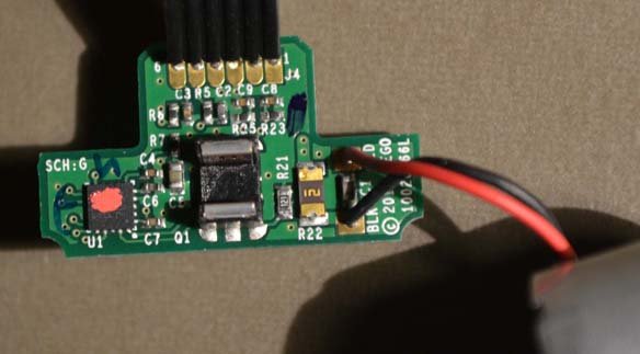
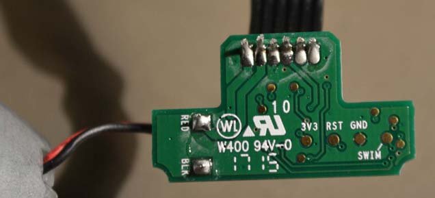
The train motor disassembly got me curious what was different from the inside of a standard BOOST motor. I couldn't find any pictures of a disassembled unit, so I disassembled my own and took photos. Board top: Board bottom: After I took the pictures, I took some acetone to the red splotch on top of the microcontroller. It turns out to be an STM8S103F2 (or maybe F3; the only difference is the amount of flash memory). The pin on the bottom of the board labelled "SWIM" is for the Single Wire Interface Module on the microcontroller. The rotary encoder sensor is a TCUT1300. ID1 goes through a resistor, then to port PD6 on the STM8 microcontroller. According to the datasheet, PD6 is "Analog input 6/UART1 data receive". ID2 goes through a resistor, then to port PD5 on the STM8 microcontroller, which is "Analog input 5/UART1 data transmit". My guess is that the ID pins are being used for serial communication between this small microcontroller and the main Hub unit -- e.g., turn on for X time/rotation/whatever. Here are additional pictures: Imgur - Lego BOOST Motor teardown