
Hod Carrier
-
Posts
1,007 -
Joined
-
Last visited
Content Type
Profiles
Forums
Gallery
Everything posted by Hod Carrier
-
 Sorry to bump this thread, but has anyone who has used Circuit Cubes motors got any feedback on the amount of power they produce? I've seen @Sariel's video testing these little critters (link below) which does seem to suggest that they are pretty powerful, but does anyone else have any views? Circuit Cubes: LEGO-compatible motors and remote control: TESTED! - YouTube
 -
Thanks for the compliment. @zephyr1934 is right about forum etiquette, but as a new member it's maybe something you weren't aware of. I'm sure many people here would be very interested to see more of your plans for your model of Antwerp Central, as it's a fabulous station in real life and would make for an amazing diorama as well as allowing you to unlock the private message function. We're also quite a helpful bunch and happy to share ideas, tips and tricks that you may find useful. The AM08 design is a bit outdated now and I think I'd want to make some changes to it before sharing it. I also don't know how strong or stable it might be because I've never built it in real bricks. I should also warn you that it is a monster at around 210 studs long and is not likely to want to go around standard LEGO curves. However, I would be happy to allow you to use the design "as is" and to modify it to suit your purposes.
-
[WIP] Merseyrail Class 777 EMU - Stadler Metro
Hod Carrier replied to Hod Carrier's topic in LEGO Train Tech
Thanks for the feedback. The cheese slope option does replicate the shape of the bumpers in that they are triangular, but I rejected the idea originally because they were too big. As you can see up-thread I did revisit the idea to see how it would look on the whole train, but I'm still not entirely convinced. Not only are they too big but there is a half plate overlap which creates a fairly obvious shadow. -
[WIP] Merseyrail Class 777 EMU - Stadler Metro
Hod Carrier replied to Hod Carrier's topic in LEGO Train Tech
Thank you for your excellent input. It's always great to kick ideas around and get the views of other builders. I totally agree that no idea is completely perfect. I've said before that the task of a LEGO builder is to find the least worst solution to any given design problem, as the building medium is necessarily restrictive. If we wanted total accuracy we would be following a different hobby altogether. My own opinion is to favour the shallow panels because it gives the cleanest finish. I agree that the hose looks good across the curved slopes and I would probably take that option except for the clips and tiles needed to secure it. As you said in your first post, it makes them look like pipes or handrails which is a view that I share. I also think that the shallow panels is the most satisfying version to design and build, even if the complexity of the structure will not be obvious to folk who see it. It's rather a lot of SNOTing and offsetting just to create what is effectively a rectangular box. There is an unevenness in the panels as presented here because of the 4L panels, but I'm currently unsure if that's a quirk of Stud.io or whether these parts really are thinner than the 2L and 3L versions as I don't have any to compare (or rather, I do but they are currently buried deep in the bowels of another build and therefore not easily accessible). If it is a difference in the part it wouldn't be too hard to use the more consistent 2L and 3L versions instead. The rounded corners may not be too visually jarring either as they are acceptable on cheese slopes and other parts. But you are right that a lot of these imperfections will disappear at normal viewing distances, especially as this is only one detail on a whole model. That's an interesting idea. I'm just not sure if it would protrude out from the shape of the curve at all as the thin part of the bracket is 2.5 plates tall and the total height of the plate portion plus the one plate recess plus the height of the thin end of the curved slope is also 2.5 plates. However, the geometry of the model does permit the cheese slopes and n x 2 curved slopes plus two plates between the bottom of the windows and the solebar, so maybe have a plate with door rail or a tile attached to the bottom of the bracket. The trade-off against that would be that it would interfere with the SNOTed livery around the cab which would require a bit more cheating with coloured vinyl. Hmm. Some food for thought anyway. -
Ah yes. That would be me.
-
[WIP] Merseyrail Class 777 EMU - Stadler Metro
Hod Carrier replied to Hod Carrier's topic in LEGO Train Tech
Perhaps a little like this. The supporting structure necessary inside the car is not that much of a compromise after all, although I have had to change some parts usage in order to retain as much as possible of the interior details. This is a comparison rendered part way halfway through the conversion showing the altered and unaltered versions of the interior. -
[WIP] Merseyrail Class 777 EMU - Stadler Metro
Hod Carrier replied to Hod Carrier's topic in LEGO Train Tech
Some real bricks at last. A quick and dirty idea of how the "toblerones" might look using each technique. What do you think? Luckily I had a quick peek at this thread before putting my bricks away again. Do you mean something like this? It is going to make the exterior walls thicker with, as you say, consequences for the interior. However, I suppose you see more of the exterior so maybe there's a trade-off to be had somewhere. I'll have a think about it. That's one idea I had considered and not pursued. I'm trying to keep this model "scale" and as faithful to the original as I can. While it would make the build much simpler I fear it may also make the resulting model a bit too boxy and too wide, and I'm not sure I wanted to go down that route. I prefer your idea of pulling in the panels that extra half plate and see if it can be made to work without having to sacrifice too much of the interior. -
[WIP] Merseyrail Class 777 EMU - Stadler Metro
Hod Carrier replied to Hod Carrier's topic in LEGO Train Tech
I don't mind one bit. If anything, I'm suffering with the opposite problem which is too much time to MOC. I had two weeks summer leave and then, just as I was about to go back to work, I got picked up by the NHS Covid Track & Trace service and have just had another week isolating (although I've tested negative). So I've had plenty of time to fill with this project. That's not a bad idea as a "cheat" which I'll keep it in mind if I come up empty with brick-built solutions. However, have a look at this first. I think this might be the new front-runner. Here's a sneaky peak inside to show how it's been done. I've had to change some of the structure in order to get the studs down orientation needed to support the panel pieces, but at least the result is clean and doesn't spoil the curve of the lower bodysides too much. I fear I may have created some structural issues elsewhere though, and the next job will be tracking those down and fixing them. Hopefully coming soon (provided that I can find enough of the right parts to do this). -
That's not a bad idea. I'm not sure that the lines wouldn't get tangled up, but it could certainly help hold the sections together ahead of the big reveal. You're very welcome, James.
-
Bless you. You're not the first to have said that to me and I doubt you'll be the last. That's certainly one option. The other I'd already considered is some form of jig into which the parts can be fitted and held in place during assembly. The design already has indents and other aids to alignment and stability during construction and I have already reduced the number of elements from it's first iteration, but I'm sure I could take it further in order to get a quicker build. Just don't place the siding near the edge of a table, though. Please...?
-
[WIP] Merseyrail Class 777 EMU - Stadler Metro
Hod Carrier replied to Hod Carrier's topic in LEGO Train Tech
Well I decided that I should try and push myself with this design. Most of the builds I have so far either have a simple livery or I have cheated with colour vinyls and so on, but this time I wanted to see whether or not I could brick build these sorts of features into the model itself. That's not to say that there won't be some cheating going on, but the extent to which I cheat will be less than before. I've gone back to the start again and, going on @ColletArrow's mention of them, decided to explore the cheese slopes one more time. Here's how it looks now. Part of the reason why I'm sticking with this approach rather than going all out for more extreme SNOTed solutions is that I want to keep the walls down to 1 brick thick to leave room for an interior and to permit articulation. Taking things up a scale might also be an option and might allow me to try a few other things like the tapering to the top of the body. I do appreciate your suggestions, though. Thank you for them. Keeping things at this scale is now looking like a quest for the least worst solution that is possible within the parts and colour palette that LEGO offers. It turns out that dark bley is not a good colour for hose and would require some relatively expensive purchases from overseas, and the double curved parts are not available in yellow. So I think it's a case of fronting up for the hose or using cheese slopes as nothing else seems to be possible. Mocking up some assemblies to check in real life is now the next step, as Stud.io renders tend to overdo the shadows and make gaps look worse. -
Thank you, gentlemen. That's very kind of you all. Ha ha!! That's a wicked idea. I love it!! The only thing I'm not so keen on is having to gather up the bits and build it back up for the next victim participant. As you can probably imagine it's not the most stable construction, although each time I built it up I improved the technique and got a little faster than the previous time. It took quite a lot of time and more than a few design revisions to get it to the point where the model would hold it's shape but still break apart in the way I wanted.
-
Just for a laugh, two little videos. Video 1 Video 2
-
[WIP] Merseyrail Class 777 EMU - Stadler Metro
Hod Carrier replied to Hod Carrier's topic in LEGO Train Tech
Got some alternative ideas to get opinions on. Merseyrail 777010 by LiamBlundell, on Flickr On the left I have swapped the bars for flex hose which means that I can reduce the number of clips used to hold them in place. In the middle I have used the 1x1 double curved slope (PN:49307) and on the right the 2x1 45 degree slope with 2/3 cutout (PN:92946). To my eyes, the flex hose version still looks like a handrail or pipe, but it does allow the use of curved slopes on the lower bodyside. Both the other versions look squarer because the curve cannot be used except where the "toblerone" is not fitted. The middle version is likely to be unbuildable anyway due to the part not being available in yellow. Thoughts...? While I'm about it, here's a small update to the build. The model will ride on #4 size wheels rather than the standard #5 in order to get the correct ride height. If my maths is correct I think I've got the spacing right in this render. On the matter of the "toblerones", the lead two cars have reduced clips as would be necessary for use with flex hose. -
[WIP] Merseyrail Class 777 EMU - Stadler Metro
Hod Carrier replied to Hod Carrier's topic in LEGO Train Tech
Thanks for the quick feedback, chaps. Yeah, I do pick some odd prototypes. There is a fair bit of SNOT in there which would make indenting the cab door tricky. In any case, the doors on the real train are flush and, apart from the droplight window and the door seals, the cab door is pretty well hidden. My intention will be to pick it out in much the same way as on the real thing, by outlining it with some thin black tape to replicate the door seals, and the same on the passenger doors too. Cheese slopes were my first attempt at a solution, but you're right to say that it affects the curve of the lower bodyside a bit too much. It really is more like a structure attached to the side of the train rather than being part of the shape. 777009 by LiamBlundell, on Flickr I've been referring to them as "Toblerones" because they look just like a line of Toblerone boxes stuck to the train. toblerone by bold-aslove, on Flickr I know my existing solution looks like a handrail or the piping down the side of a steam loco, and that's why I'm not very happy with it. I like your suggestion and can see how that would work, but it would mess somewhat with the proportions and require a fairly hefty redesign. I'll have a tinker later and see if I can make it work somehow. One tweak that I did come up with was to use flex hose. Unfortunately the rigid stuff doesn't come in dark bley and any rod longer than 4L has a molded collar that would prevent it from fitting. At least flex hose would mean that I could reduce the number of clips I'm using which might help to clean up the appearance a little. -
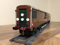
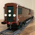
This is a model that I've been working on for a while but have only just got to the point of near completion. It was one of those projects that started quickly only to hit a wall and then sit idle for several months before coming back to again later, but I'm now at the point of asking for comments and feedback on some of the design choices I've made. The model is of the brand new Class 777 EMU that is currently undergoing testing before entering service on the Merseyrail network. Built by Stadler in Switzerland and based on the Stadler Metro platform, these trains will replace the existing fleet which has clocked up around 40 years of service. These trains will run on the existing 750V DC third rail electrification system but have the capability to be modified to run either on battery power away from the electrified network or on the 25kV AC overhead electrification, making new services possible. Class 777 777010 - Kenilworth Road, Ainsdale. by Martyn Hilbert, on Flickr My design is for a static model rather than a powered one, which permits a full interior. However, the model will still articulate at the bogies and between the cars. Apologies for the way that Stud.io renders transparent parts. They tend to show almost black, but I promise you that details like the headlights and cab windows really are there. The design is as good as finished, but I'm wondering if there are better ways to convey some details. The one I'm struggling with most is what looks like handrails along the lower bodyside but which are my attempts to replicate what I have been calling the Toblerones along the flanks of the real train (I presume that their function is to help prevent passengers falling between the train and the platform). They are an obvious detail that I don't think I could omit but they are not huge structures. I'm just not sure if I've gone about them in the right way. Also, the livery is a bit complex around the cabs and has required the use of some illegal building techniques in order to complete it as shown here. The primary component in this section is PN:92946, but some will require cutting down to 1x1 in order for the livery to work. Thoughts...? Comments...? Feedback...?
-
@ScotNick @coaster Thank you gentlemen for your swift and informative replies. The L-Gauge website page isn't fully up to date with regard to the offerings currently on the market, nor does it reflect the information contained within this thread, and doesn't actually mention the size I'm particularly interested in. However, it is a very good resource. As for the .dat files, I am content to wait and see what @supertruper1988 comes up with when he gets the time to complete the project. Hopefully he is going to include sizes smaller than #5, but clearly he has much more pressing priorities to attend to first, and it's right that what is a hobby activity needs to wait. Thanks again.
-
Apologies for boosting an old thread. I notice that the table shows the tread diameter in both mm and plates. How much extra should I allow for the wheel flanges to permit clearance against bodywork, etc? Is it 1 plate on each side (2 plates in total) or does the flange depth vary? Also, on a not unrelated note, is anyone out there working on .dat files for the various sizes to permit them to be imported into your digital building software of choice? I know that some wheels are already available to download (e.g. BBB) but I would be interested in other sizes also. Thanks.
-
Compact Locomotives with Large Technic Motor 88013
Hod Carrier replied to ejayb's topic in LEGO Train Tech
You may already be aware of this, although I wasn’t until I’d got hold of some 88013 motors. It’s 8 studs long compared to the old PF L-motor which is 7 studs long. Standing one upright is going to make any model quite tall, especially once you’ve added any gearing to drive the axle. -
[MOC] Differential Drive - Variable Reduction Gearing
Hod Carrier replied to Hod Carrier's topic in LEGO Train Tech
I'm glad you're not trying to be destructive because we're not going to fall out over this. I will just say again, however, that I am not trying to get more power or speed out of this idea. That was never the idea to begin with. It is just a way of trying to give LEGO trains a larger usable range of speeds by means of a compact variable reduction gearing. I am also well aware that some PU motors allow for slow-speed control due to the in-built rotation sensors, but would remind you that this functionality is not currently fully supported by the 2 I/O "City Hub" that is favoured by train builders due to it's size compared with the more capable 4 I/O Technic Hub. It's also worth stating again that this idea is not specific only to PU but can be used with any Technic motor and is, therefore, of potential use to those builders still using PF motors. I understand that you consider this idea to be useless, and that's fine. Not every idea is going to resonate with every builder and I accept that there is always likely to be a whole range of reactions. Some builders may be happy to embrace third party electronics and other components in order to achieve certain functionality, but not everyone is confident to follow that path, and I include myself in this. I simply wanted to explore another path to achieve these outcomes that falls more easily within my comfort zone. -
[MOC] Differential Drive - Variable Reduction Gearing
Hod Carrier replied to Hod Carrier's topic in LEGO Train Tech
Just a little update, if I may be permitted. The Fairbanks Morse H10-44 switcher has had an upgrade and now uses Technic L-motors. It's a wee bit of a squeeze and routing the cables was a bit of a headache, but everything goes in nice and snug. I'm sure that there is a better arrangement of parts, but I wanted to keep the motors away from the bogie pivots so that they could be lowered enough to permit them to be stacked. The problem otherwise is that the motors would have needed to be raised in order to give enough clearance for the bevel gears that drive each bogie. The arrangement of gears and shafts for the differential is the same as that used on the English Electric GT3 but it retains option to swap the final gear ratio between 1:1 and 1:3. This is done by sliding different gears along the prop shaft to engage with the differential which can be accessed through a hole left in the floor of the loco. A little spin on the test track to show that the loco is now capable of turning the higher 1:3 gearing and the range of speeds that can be achieved. In spite of all the effort put into the Powered Up custom controller to make use of the L-motor's rotation sensor to adjust it's speed, this run has been done without making use of this capability. Instead I have used the simple version of the controller that just feeds the motor power variables directly into the motors using the SetPower command. As you can see, it still manages a good range of power and control thanks to the greater power of the larger motors. In other developments, I did try pairing an XL-motor with an L-motor on the GT3 chassis using the existing gearing. It was a bit of a lash-up and certainly wouldn't fit inside the bodywork, but it was functional. Taking @zephyr1934's idea of running up the XL-motor first as a low-speed high-torque starter and then adding the L-motor for high-speed running, the loco performed well but didn't quite have the same range of low-speed control. I'll test some more, but I suspect that some sort of hybrid control system where the second motor turns the differential in reverse to increase the reduction ratio in the gearing would replace this loss of truly low-speed capability. Whether the additional grunt of the XL-motor offers other advantages, such as increased hauling ability, is something someone with access to more rolling stock would have to test. Also still to be tested is gearing-up the L-motor ahead of the differential to see what difference this makes. -
Whenever I go into a LEGO store to buy bits I am always asked by the staff who serve me what it is that I'm building. Because this happens every single time I am convinced that they are just carrying out a company instruction to show interest, so I always give vague answers like "something grey" or "something motorised" depending on what my purchase was on that day because actually they don't care what I'm building. However, overhearing some of the conversations they have with other customers it is clear that at least some of the staff are knowledgeable and interested and aware of the wider LEGO community resources such as Bricklink and I feel happier talking more expansively with them. It got me wondering to what extent LEGO shop staff really have an interest in the hobby and to what proportion it is simply a job. Also, are my feelings towards them shared with others in the community or am I just being a grumpy cynical old man who really ought to lighten up?
-
[MOC] Differential Drive - Variable Reduction Gearing
Hod Carrier replied to Hod Carrier's topic in LEGO Train Tech
Having tried a pair of M-motors with the differential I’m unsure of their suitability for high speed application. I simply couldn’t get them to turn a 1:3 ratio even with both on full power. Even at lower speeds (assuming it could be made to move at all) I’d find that either one motor would stall or the inertia in the drivetrain below the differential would be so great as to cause the two motors to simply spin their power away through the differential. I still haven’t modified the H10-44 to take L-motors, so I may try a few things first in it’s initial configuration to see whether I can improve it's performance. There may be an advantage to mismatched motors as you suggest, with L and XL being the most likely combination. I can feel my credit card trembling with fear already. -
[MOC] Differential Drive - Variable Reduction Gearing
Hod Carrier replied to Hod Carrier's topic in LEGO Train Tech
That’s precisely it. The code as it stands has 41 evenly spaced power steps in total (stop plus 20 steps to full power in each direction). This is likely to need a bit of tuning to suit the characteristics of different motors in order to give a smooth transition through the acceleration/deceleration phase. Rather than increasing the speed of each motor individually as you suggest, the custom controller treats both motors as a single system. The buttons only increase and decrease train speed “a” which is resolved into the individual motor inputs “b” and “c” by the program. That said, you probably could drive the system manually through a remote by increasing and decreasing the motor speeds individually with the buttons, but I think you’d lose some flexibility. As you can see from the motor map graph, there are times when motor A is driving in reverse at 50% speed relative to motor B. This acts to increase the ratio of the reduction. I think that sounds workable. -
[MOC] Differential Drive - Variable Reduction Gearing
Hod Carrier replied to Hod Carrier's topic in LEGO Train Tech
My apologies. I was just a bit concerned that the direction of the technical discussion was moving towards the models operating just like the Fell Loco, and I wanted to bring it back away from that. As it happens, I did come up with a motor and differential arrangement that might fit inside an 8-wide body, but I’m not sure how practical or successful it might have been. Yes, I think it could be done. Would you change over from one motor to the other at a certain speed or run both simultaneously during the high-speed phase? My feeling is that you’d have to keep a careful eye on the gearing. If you run only one motor at a time you’d have to remember that the differential will automatically apply a 2:1 reduction, so you’d have to look carefully at the ratios for the motor inputs. You’d also be increasing the complexity of the geartrain with it’s consequences for internal friction.