

BrickTronic
-
Posts
81 -
Joined
-
Last visited
Content Type
Profiles
Forums
Gallery
Posts posted by BrickTronic
-
-
1 hour ago, Chris Hocking said:
Thanks for this information Jo!
...USB-Serial Controller : Product ID: 0x23a3 Vendor ID: 0x067b (Prolific Technology, Inc.) Version: 6.05 Serial Number: CVDYf146B11 Speed: Up to 12 Mb/s Manufacturer: Prolific Technology Inc. Location ID: 0x00100000 / 1 Current Available (mA): 500 Current Required (mA): 100 Extra Operating Current (mA): 0 USB HS Serial Converter: Product ID: 0x6001 Vendor ID: 0x0403 (Future Technology Devices International Limited) Version: 4.00 Serial Number: FTC87U6C Speed: Up to 12 Mb/s Manufacturer: FTDI Location ID: 0x00120000 / 3 Current Available (mA): 500 Current Required (mA): 44 Extra Operating Current (mA): 0
FTDI usually are USB to TTL Converters that still need RS232 Level-Translater like an MAX232 compatible Chip
Does your Adatper have an 9-Pin Sub-D connector on the RS232 side or only single Wires for Bread-Board use ?guard let port = selectedPort else { return } port.baudRate = 2400 port.numberOfDataBits = 8 port.numberOfStopBits = 1 port.parity = .odd port.usesRTSCTSFlowControl = false port.usesDTRDSRFlowControl = false port.dtr = true port.rts = true port.delegate = self port.open()
Please try DTR Pin-4 Low (False)
Jo
-
Hello,
What Settings did you use for DTR (Pin 4) and RTS (Pin 7) of Sub-D connector at RF-Tower ?
See Schematic
There is needed +12V on DTR (Low in UART-Register) and -12V on RTS (High)
Jo
-
On 6/3/2025 at 10:13 PM, vicocz said:
Hi, I maintain personal fork of BC2 and as it looks the original repository is somehow out of maintanence right now, I'm having my own builds and releases. Recently I've added base support for PFX for my own as my PRs to the original reporitories are not getting merged. There are additional features from other contributors as well. E.g. MouldKing support.
Have a look here, if you are interested: https://github.com/vicocz/brickcontroller2/releases
Regards
Vit
Hello,
I like your enhancements.
Does you have an overview what Modules (MK4, MK6, ...) will dvertise what data ?
Or does these Modules not advertise and can not be "seen" by BLE-Master ?Will here also supported the New MK-H4.0 & ML-H6.0 Boxes ?
Does the "Blade-Hall" Boxes (MK-BH4.0 & MK-BH6.0) use same Commands like the H4.0 / H6.0 Batteries ?Jo
-
On 4/1/2025 at 7:05 AM, ruppie said:
Hello all,
a short while ago i have noticed this project:
Home | MULTI-Module Documentation
https://github.com/pascallanger/DIY-Multiprotocol-TX-Module/
It is about an RC trasmitter interface module based on 4 different transceiver chips.
As as result plenty off different RC protocols can be supportet here.
Since the presentation of ELRS you may it obsolete for future use in the RC sector, but as long as their are the huge number of receivers on the market with their own brand specific protocols i think it is still usefull.
What is this all about according to brick sets ?
I was suprised to see that at least Mould King is supported here ,too: https://github.com/pascallanger/DIY-Multiprotocol-TX-Module/blob/master/Protocols_Details.md#mouldkg---90
As a result, if you are using MK Battery Boxes V4 or V6, you can choose from a wide varity of RC Transmitters to control your brick build models.
What is the idea behind: Using the capabilities of the transmitters, as well as option to put additional lua scripts to create more convinient user expereinces and increase the overall play factor.
...
Hello,
Looks interesting.
Are there detailed technical informations available how it is working ?
is the 1MHz (like Bluetooth Clasic) or 2MHz (like BLE) spacing between Channels ?
Is there used Channel-Hopping like Bluetooth ?
What does following Example mean :
            //Example:    TX: C=11 S=Y A= 4B 44 48 P(7)= C0 37 02 4F 00 00 00
            //            RX: C=76 S=Y A= 4B 44 48 P(7)= 5A 37 02 4F 03 0D 8E
            // 03 0D 8E => RF channels 0F,1C,39,3C
what does "binding" mean and how does it work ?
How does "Binding" Sequence look like ?One Module contain 4 or 6 Data-Bytes, how are 16-Channels (4x 4-Port Hubs) controlles simultanous ?
Jo -
2 hours ago, Phondly said:
Hello,
Can you please add technical Description of this Battery ?On your Site I found only Info that Li-Ion has 15Wh
At Single-Cell at 3,7V this would be 4AhWhat Type of Battery does you use ?
How long does charging by USB take ?
What USB Current-Capability ? classic 500mA only ?When I want to use our Battery with Battery-box 88015, what protection is included (shortaged Load or stalled Motor) ?
What is with Overtemperature (charging), Over- Under- Voltage ?Jo
-
2 hours ago, Bliss said:
...
But as far as I remember, the serial/Infrared link between the PC and the RCX was only to send a program to the CPU inside the RCX (and to update/upload the firmware).
...Hello,
When you check the Firmware-Command-Overview that is part of the SDK (can be downloaded on Philos' Page) then for each command there is stated if this Command is "Direct", or "Program" or both.
So most commands can be used inside a to RCX downloaded Program or to be executed imediate after IR-Reception. Therefore a "Reply" is usually specified, that in a Program-Execution is not needed.Jo
-
23 hours ago, JopieK said:
...
LEGO uses a TI microcontroller in Powered Up, I hope they move to e.g. STM32 which makes it easier to extend the custom firmware options :)
...
Hello,
There are STM included :Part Set HUB Name uC Program Memory Remark 45509 31313 IR Seeker STM8S103F3 Flash 8K 45504 45544 Ultrasonic STM8S103F3 Flash 8K 45505 45544 Gyro STM8S103F3 Flash 8K 45301 45300 Wedo 2.0 CC2540 Flash 128K 88006 17101, Boost Move STM32F070RBT6 Flash 128K 75273 CC2640 Flash 128K 88009 ... City/Train Hub STM32F030RCT6 Flash 256K CC2640 Flash 128K - 10874, Duplo CC2640 Flash 128K 6V Battery 10875, 45025 88012 ... Control+ STM32L431RCT6 Flash 256K CC2640 Flash 128K 45601 45678 Spike Prime STM32F413VGT6 Flash 1M CC2564C - - CC2564 SPI to BLE Bridge 88016 51515 Robot Inventor STM32F413VGT6 Flash 1M CC2564C - - CC2564 SPI to BLE Bridge 45609 45345 Spike Essential STM32F413VGT6 Flash 1M CC2564C - - CC2564 SPI to BLE Bridge 88010 ... Remote CC2640 Flash 128K 6V Battery - 71350, Mario CC2642R Flash 352K 3V Battery 71439 - 71387, Luigi CC2642R Flash 352K 3V Battery 71440 - 71403, Peach CC2642R Flash 352K 3V Battery 71441 - 42176 TechnicMove CC2642R Flash 352K 3,7V Li-IonJo -
13 hours ago, Toastie said:
...
- The rotation sensor thresholds for the "four states" per 1/4 clockwise revolution are 1023/784/354/536 A/D units corresponding to 4.8/3.7/1.7/2.5 Volt. I simply watched the A/D values
...
Thorsten
Hello,
your values looks strange.
When you divide Voltage by ADC-Result there should remain Voltage of a LSB :
3rd Line is 1 LSB in mV
and 4th Line is LSB * 1024 Full-Scale ...I would have expect 5,00V as ADC-Reference taken from 5V linear Regulator and not less, something arround 4,8V ...
Jo
-
20 hours ago, Toastie said:
Dear all,
more timing and some other data on #9751:
-
A serial port buffer is filled with 8192 bytes in about 9.6 +/- 0.2 s (used my QBasic program and watched for IF LOC(1) > 8191 THEN STOP with a 8192 long serial input buffer, did not read anything, just waited for the program stop along with my cell phone timer. Took a few replicates ... this is absolutely not elegant but quick ...
In other words, 8191/19 = 431 19 byte long data frames are emitted in 9.6 s = 45 frames per second. Every 22 ms such a frame arrives. - One 19 byte data frame is (see above) 20 ms long.
- #9751 samples the input ports for 130 us every 3.3 ms (used my very low profile digital oscilloscope).
- Within 130 us, all 8 inputs of #9751 can be sampled, as the total sampling/conversion time for the microcontroller's ADC is 13 us (as per data sheet).
- 3.3 ms x 3 = roughly 10 ms are required for a 3 bit increment in the internal "counters" for the light and rotation sensors.
- During sampling, the input port voltage is 5.0 V (10k internal pull-up resistor, see my last post), the remaining time it is 7.5 V for active sensor "charging".
- When "shorting" an active input with a 9V lamp, it "glows" a little; "shortening" it with a current meter results in a current of 15.9 mA which is the max. current provided by each input of #9751, as was reported by Mark Bellis for the RCX inputs.
That's it for the moment
 maybe @Bliss, @BrickTronic or anyone else of course may want to check my calculations/assumptions? I tend to screw up such things regulary ...
Best,
ThorstenHello,
nice update-
9,6s / 431 Frames = 22,27ms @ 190 Bit (19 * (1+8+1)) -> 117,23us/Bit => 8530,2Bd
but : 50Hz (20ms per Frame) * 19 Byte = 950 Byte/s => @ 8192Byte -> 8,623s
so 1s difference seems more than response-time issue because manual start/stop cell-phone timer usage ...
Can you measure the real Baudrate (Oszilloscope) and the Frame-Repetition Frqueency ?
-> does we really have 20ms per Frame ? - OK
- Your measurement of 3,3ms with 130us is longer than Philo has evaluated for the RCX (3,0ms / 100us)
-
for 10-Bit Values 2 AD-Conversions are necessary (2x 13us * 8-Channel),
and there has to be added also overhead in Interrupt Routine (save/store Register; modify DAPR and Multiplexer Register ...)
not enough time for all 8 Channels
different handling of active and passive sensors might not the case and makes Code more complicated
(remind Status-Bit evaluation between Rotation, Light Switch & Temp seem to use same Thresholds)
I assume that 130us measurement-slot has offset between previous and next channel
=> this can be evaluated by Oszilloscope -
within a 20ms Frame there would be 6 Sensor-Readings but unly 3 increments can be communicated
maybe some kind of Filtering ? or to supress spikes (changed Votage only accepted when following measurement is in same range ?) - did you measure "after" Bridge-Rectifier (+1,4V = 2x Diode-Drop) at Sensor or was this read from Oszilloscope Screen ?
- OK
Jo
-
A serial port buffer is filled with 8192 bytes in about 9.6 +/- 0.2 s (used my QBasic program and watched for IF LOC(1) > 8191 THEN STOP with a 8192 long serial input buffer, did not read anything, just waited for the program stop along with my cell phone timer. Took a few replicates ... this is absolutely not elegant but quick ...
-
15 hours ago, Toastie said:
...
This results in a max. resolution of 3 ticks x 45 data emissions/s = 135 ticks/s for rotation sensor counts
...All the best,
ThorstenHello,
45 data emissions ????
where does this 45 come from ?9600Bd is 104,16us per Bit, Start + 8-Data + No-Parity + Stop are 10 Bit per Byte and 19 Bytes (190 Bit). So 19,7916ms for a Data-Frame.
-> so 20ms repetition of the Frame3 detected 1/16 rotations every 20ms (50Hz) is 50*3/16 rotations = 9,375Hz (rotations) or 562,5 rpm
Can you tell me how you evaluated 135 of 1/16-ticks per second instead 150 ?
Jo -
18 hours ago, Toastie said:
...
Does anybody have further information?
...
Best regards,
ThorstenHello,
On this Web-Page there you might find detailed informationJo
-
49 minutes ago, AJB2K3 said:
Got a response now just need to decipher the ports

maybe this info might help you
-
Hello Thorsten,
Again a great project from you. I like them. Please keep continuing.But in your Matrix-Picture the "ON" Button should be the "B" Button and Cols C18 to C27 seems mirrored to C27 to C18
The only 680x uC in PLCC28 I could find was the MC6805P2FN (Motorola) or EF6805P2FN (SGS later ST)
For the H-Bridge marked NOD-1001 I could not find a Datasheet.
But this driver seems to be used also in RS232 Interface "B"Jo
-
2 hours ago, imurvai said:
Yeah, without having the new hub I can't tell. I'm planning to buy it sometimes soon and then I can look into it.
Hello,
There are first findings :
Pybricks
Daniel Benedettelli
"toorisrael"
Jo -
1 hour ago, JusTiCe8 said:
Hi,
it's a very old post sorry, does anyone still have disassembly pictures please ?
@mostlytechnic maybe ? Your website looks to be down unfortunately.
Thanks.
Hello,
You can try Jetro's Overview or here ...
Jo
-
2 hours ago, Lego Tom said:
I found plugs on line. I can figure out the rest with an ohm meter. Thanks.
Or look at Philo
Jo
-
4 hours ago, MisterCreators Custom MOCs said:
I now tested everything again and built a small testing rig, to make sure that it's nothing wrong with my RC Box. But same as before, the servo still only turns all the way to the left or to the right, no proportional steering possible. I used an 2S lipo to make sure that I'm not overvolting my servo.
Hello,
When Lego-Servo is working with Lego-IR-Rempte, then PWM of the IR-Remote should be OK
In an Youtube-Video (Time-Stamp 0:45) you can find Measured this PWM.
There are 3,5 sections of 250us resulting in a PWM-Period of 875us that is about 1,14kHzWhen you System is using higher Frequency, then the Servo has Problems getting the right %-Value
Jo -
2 hours ago, NoEXIST said:
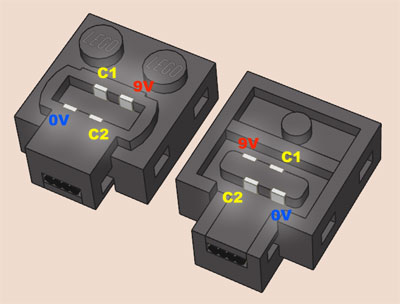
Not sure, but C1 and C2 are just to power electronics used in servos and PF receivers. As I know they don't work exactly the same as regular motor contacts do
Hello,
PF-Receiver and Lego-Servo are powered by GND/0V and 9V Pins of the Power-Function connector.
See here again Picture from Philo :
Signals on C1 and C2 at Servo define Direction and Angle
A simple H-Bridge-Driver (that is inside the Power-Function IR Remote Receiver) that usually control an DC-Motor can generate this Sinals for the ServoJo
-
11 hours ago, MisterCreators Custom MOCs said:
Yes I did, but the servos don't understand the PWM signal the ESCs put out. So for now servos can not be controlled proportional, but they can be controlled left or right (-90°, 0°, 90° only these 3 positions and nothing in between)
Hello,
Your Statement is valid for many cheap chineese Servo-Clones
Beside "Center" the Lego Servo support 7 Positions to the Left and 7 Positions to the Right.
In total 15 Positions.Unfortunately Lego uses not the "usual" Servo-Control (20ms Periode and 1,0 to 2,0ms High.
Center is 1,5ms and +/-0,5ms for Left/Right (depend on Servo if this result in +/- 270° angle or only +/- 90°)Lego drive C1 = 0 and C2 0 to 100% PWM
or C2 = 0 and C1 0 to 100% PWMIn an Youtube-Video (time-Stamp 0:52) you can see an opened Lego-Servo and the 15 Positions for Position-Control/Regulation
Jo
-
18 hours ago, MisterCreators Custom MOCs said:
... The Dual Channel configuration allows to control two motors separately over one PowerFunctions Connector. .....
Hello,
I assume, your PF-Adapter wires GND from Bottom to C1 on Top and 9V (BAT+) from Bottom to C2 omn Top, right ?
I've borrowed from Philo's Page :
So your RC-Box put PWM (lets call them C3 & C4) to the PF-Connector instead GND & 9V.
Does you conform ?I would be interested, why your Box is so high ?
What is inside ?Jo
-
21 hours ago, Lok24 said:
or all together ;-) Perhaps @TexasEngineer454 should open a new thread and ask for others to add lists like that:
42099	4x4 X-treme Off-Roader
Port A	XL	front drive	white
Port B	XL	rear drive	red
Port C	L	steering	blue
Hub System ID Set Port Ids ---------------------------------------------------------------------------------------------------- Control+ Control+ 0x80 42099 4x4 Offroader A 0x2F XL-Motor (white) “Drive Front“ B 0x2F XL-Motor (red) “Drive Rear“ C 0x2E L-Motor (blue) “Stearing“ D - 42100 Liebherr A Top : 0x2F XL-Motor (red) “Arm“ Bot : 0x2F XL-Motor (red) “Chain Left“ B Top : 0x2E L-Motor (yellow) “Stem“ Bot : 0x2F XL-Motor (yellow) “Chain Right“ C Top : 0x2E L-Motor (blue) “Bocket Tilt“ Bot : - D Top : 0x2E L-Motor (green) “Bucket Open“ Bot : 0x2E L-Motor (green) “Rotate“ 42109 Top Gear Car A - B 0x2E L-Motor (red) “Steering“ C - D 0x2F XL-Motor (yellow) “Drive“ 42114 6x6 Volvo Hauler A 0x2F XL-Motor (blue) “Drive / Tilt“ B 0x2E L-Motor (green) “Gear-Box“ C - D 0x4B L-Angular (orange) “Steering“ 42124 Offroad Buggy A - B 0x2E L-Motor (-) “Steering“ C 0x2E L-Motor (-) “Dive“ D - 42129 Zetros A 0x2E L-Motor (blue) “Drive 1“ B 0x2E L-Motor (red) “Drive 2“ C 0x01 M-Motor (green) “Differentisl Lock“ D 0x2E L-Motor (white) “Steering“ 42131 Cat D11 Bulldozer A 0x4B L-Angular (red) “Chain Left“ B 0x4B L-Angular (yellow) “Chain Right“ C 0x2E L-Motor (green) “Blade- Lift/Tilt / Gripper-Lift / Stair“ D 0x2E L-Motor (blue) “Gear-Box“ 42140 Transformation Vehicle A 0x2E L-Motor (violet) “Chain B“ B 0x2E L-Motor (teal) “Chain A“ C - D - -
2 hours ago, AVCampos said:
The easiest solution for TLG would be to make an "analogue" version of the train controller, something in the lines of MK's 6-way controller. Then it'd just be a matter of Pybricks in the hub interpreting the inputs as needed.
...Hello,
Does anybody know what is inside thie MK 6-chanel Remotge ?
Can the used uC be replaced by another uC suporting Microphyton and therefore also Phybricks ?
An Arduino Nano BLE 33 with the NRF52840 would be such an candidate in my eyes.
Jo
-
2 hours ago, Toastie said:
...
As I could nowhere find schematics for the 9771 Lego Interface 1 ISA bus card
...
If not found anywhere else, I'll post the 9771 schematics here.
Best
ThorstenHello,
9771 Schematic was reverse engineered hereAnd you can control the Interface "A" also by your parallel LPT Port
Jo
-
On 11/20/2022 at 2:10 PM, Toastie said:
...
Here you go:
...
This document (PDF) may be a matching datasheet - it is from Toshiba, from 1999, it covers 8-bit microcontrollers, and it has an onboard LCD driver. But who knows, TLG is always making big secrets about their electronic chippies:
https://brickshelf.com/gallery/ThorstenB/ThisAndThat/SCOUT/tmp86cm29u.txt
(You need to rename the .txt extension to .pdf - Brickshelf does not like PDFs to be uploaded).
Best regards,
ThorstenHello,
@Toastie : Again many Thanks.
The Data-sheet might be an Delta Data-Sheet.
Big surprise that it has 10-bit ADCI digged a little bit and found a Data-Sheet for TMP86CH29BUG
My conclusin on this ans some other similar documents is :
QuoteTLCS-870/C Series
based on Intel 8080 (/ Zilog Z80) Registers
TMP86CM29_U_
!! !!!
!! !!+-- G : tbd
!! !! B : tbd, Emulation Chip
!! !! : no feature
!! !!
!! !+--- U : PQFP64 0,5mm Pitch
!! ! F : PQFP64 0,8mm Pitch
!! ! X : Bond-Out Chip, Emulation Chip
!! !
!! +---- A : tbd, Emulation Chip
!! L : Low-Voltage, max 3,3V instead 5V
!! B : tbd
!! : no feature
!!
!+------- M : 32k
! H : 16k
! 8 : 8k
! 9 : external, Emulation chip TMP86C929AXB
! 4 : 4k
!
+-------- C : Mask
F : Flash
P : OTPSo Linked more detailed Data-Sheet might fit.
Jo

 maybe
maybe 
Reverse Engineering Lego Technic CyberMaster C2
in LEGO Technic, Mindstorms, Model Team and Scale Modeling
Posted
Hello,
I confirm. The (RCX) IR-Tower uses also RTS=High/True to have -12V (-3 to -12V) on Pin-7 of 9-Pin Sub-D connector to secure propper RS232 Level on TXD Pin 3 to your Computer
Does you remind the Schematic
Your Projects like your MulPi shows, that you are much more than an apprentice :-)
Jo