DrJB Posted February 28, 2014 Posted February 28, 2014 (edited) Two designs I thought up ... 1. A free wheel transmits rotation only in one direction, and is free to spin in the opposite direction. 2. A flex-coupling is well ... meant to absorb misalignments and quench torsional vibrations Both designs are rather sturdy (for rigidity) and may be simplified. FrWheel and FlexCoupler.lxf Edited February 28, 2014 by DrJB Quote
DrJB Posted March 1, 2014 Author Posted March 1, 2014 (edited) 145 views ... 17 downloads .. and not a single answer? Sorry guys, despite the thread title ... this is NOT about giving away FREE parts ... lol Edited March 1, 2014 by DrJB Quote
0RBlT Posted March 1, 2014 Posted March 1, 2014 Hello! Frankly I downloaded once and watched your theme! But I can not say, because I do not understand why do we need this mechanism! Differential, sliding bridge, drive it, I understand why you would need a car model, but where and how to apply your design I can not imagine! Maybe I do not understand, and if I'm wrong then please give me an answer that I could understand and maybe then I could say something (comment) or advise! Quote
piterx Posted March 1, 2014 Posted March 1, 2014 it's similar to mine...except for the fact that you're using those 8th gears wich are completely useless :P Quote
DrJB Posted March 1, 2014 Author Posted March 1, 2014 (edited) Hello! Frankly I downloaded once and watched your theme! But I can not say, because I do not understand why do we need this mechanism! Differential, sliding bridge, drive it, I understand why you would need a car model, but where and how to apply your design I can not imagine! Maybe I do not understand, and if I'm wrong then please give me an answer that I could understand and maybe then I could say something (comment) or advise! FreeWheels and Flexible Couplers are often used in off-highway and industrial applications. I did not imply they must be used on your typical lego cars, but nonetheless. those are rather wide-spread mechanisms. A free-wheel transmits rotation in only one direction (and there is one in your bicycle). Try and build it, and you'll see that the input/output shafts (axles) rotate together only in one direction. If you reverse the direction, the connection is lost. As for the flex coupler, typical internal combustion engines do not run at constant RPM. There is torsional oscillation/vibration superimposed onto the average RPM. A flex-coupler is typically used to absorb/reduce such oscillations. You will not see such oscillations with any of the Lego PF motors. Lastly, my interest in Lego is not to build nice looking cars ... I'm in it primarily to reproduce real-life mechanisms, and the freewheel and flex-coupler do exist in real life. it's similar to mine...except for the fact that you're using those 8th gears wich are completely useless :P Not quite, it seems you missed the point about the use of 8t gears (in my specific contraption). From what I can guess from your picture, your design is essentially a flex coupler as the rubber elements are connect on both sides. In my design however, the gears make the rubber parts rotate and push harder against the contact surface, to increase the grip. The harder you twist, the higher the friction, and the higher the torque you can transmit. It is VERY different from your design. Also, my design transmits zero torque/motion in the opposite direction, and that is why I called it 'freewheel'. Check out the site below to understand how a freewheel works http://en.wikipedia.org/wiki/Freewheel Edited March 1, 2014 by DrJB Quote
legomuppet9 Posted March 1, 2014 Posted March 1, 2014 FreeWheels and Flexible Couplers are often used in off-highway and industrial applications. I did not imply they must be used on your typical lego cars, but nonetheless. those are rather wide-spread mechanisms. A free-wheel transmits rotation in only one direction (and there is one in your bicycle). Try and build it, and you'll see that the input/output shafts (axles) rotate together only in one direction. If you reverse the direction, the connection is lost. As for the flex coupler, typical internal combustion engines do not run at constant RPM. There is torsional oscillation/vibration superimposed onto the average RPM. A flex-coupler is typically used to absorb/reduce such oscillations. You will not see such oscillations with any of the Lego PF motors. Lastly, my interest in Lego is not to build nice looking cars ... I'm in it primarily to reproduce real-life mechanisms, and the freewheel and flex-coupler do exist in real life. Not quite, it seems you do not understand the use of 8t gears. From what I can guess from your picture, your design is essentially a flex coupler as the rubber elements are connect on both sides. In my design however, the gears make the rubber parts rotate and push harder against the contact surface, to increase the grip. The harder you twist, the higher the friction, and the higher the torque you can transmit. It is VERY different from your design. Also, my design transmits zero torque/motion in the opposite direction, and that is why I called it 'freewheel'. Check out the site below to understand how a freewheel works http://en.wikipedia.org/wiki/Freewheel I believe they are the same, they serve the same purpose, yours is just less compact although I am no expert Quote
skppo Posted March 1, 2014 Posted March 1, 2014 Piterx uses centrifugal force to engage the wheel. The rubber is not connected on both sides. Quote
DrJB Posted March 1, 2014 Author Posted March 1, 2014 (edited) I believe they are the same, they serve the same purpose, yours is just less compact although I am no expert A centrifugal coupler and a free wheel are NOT the same thing ... A centrifugal coupler engages when the rpm reaches a certain value ... A freewheel engages in only one direction, no matter how small or large the rpm is. Edited March 2, 2014 by DrJB Quote
piterx Posted March 1, 2014 Posted March 1, 2014 mine is a frewheel...i just cheated using half stud to fill the rubber parts otherwise it could get stuck if too much torque is applied... 10 minutes ago i just discovered something that is so stupid that i've never thought about it... the clutch and the gearbox have to run at the highest RPM possible and at the lowest torque so they never have problems xD Quote
jantjeuh Posted March 1, 2014 Posted March 1, 2014 (edited) The design for the free-wheel/coupler/one-way clutch is a common one, have seen it used in several MOCs. Edited March 1, 2014 by jantjeuh Quote
legomuppet9 Posted March 1, 2014 Posted March 1, 2014 Piterx uses centrifugal force to engage the wheel. The rubber is not connected on both sides. ooooohhhh.... thank you for clarifying Quote
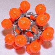
Boxerlego Posted March 1, 2014 Posted March 1, 2014 Good work! I've seen flex coupling used for the motors that power washer machines. My question is where is the input shaft at here, is it the blue gear. Quote
DrJB Posted March 1, 2014 Author Posted March 1, 2014 (edited) For the free-wheel, the input shaft is the one on the right (the one with the 8t gear). For the flex coupler (not shown, only in LXF file), it does not matter, as each shaft can be either input/output as the assembly is symmetric. Sorry can't post a pic of the flex coupler as running low on posting allocation. Edited March 2, 2014 by DrJB Quote
legomuppet9 Posted March 2, 2014 Posted March 2, 2014 Sorry can't post a pic of the flex coupler as running low on posting allocation. you can upload photos to somewhere like flickr and then copy the images across instead of attaching the images Quote
skylinedan Posted March 2, 2014 Posted March 2, 2014 I downloaded the file, had fun taking it all apart and putting the pieces all over the table top, :) Quote
Splat Posted March 3, 2014 Posted March 3, 2014 @DrJB - have you tried making your free wheel design using real pieces? I built this free wheel on the weekend (based on the pic in the first post), and while it 'sort of' works, there are a few problems that still need working out: First, the section in the middle is just 'floating' there. In real life it isn't being supported by much, and tends to wobble and twist a little bit when everything is spinning. Secondly, the Axle Connector Double Flexible (Rubber) pieces tend to flip the wrong way when too much resistance is applied to the output, basically reversing the direction of the free wheel. I think this is why piterx inserted those modified 1L axles - to prevent the rubber parts from flipping the wrong way. In your design, it doesn't help that the 8T gears are 'trying' to make them flip too. If you have built this and it it working better for you, I'd love to see a video of it in action. Quote
DrJB Posted March 3, 2014 Author Posted March 3, 2014 (edited) Yes I did build it and it works fine for me ... I'll try to make a video and post it tonight. Have you looked at the LXF file and made sure you got everything built as I intended? Yes, the middle part IS floating but it can be supported better and that'll make the design a bit bulkier ... nonetheless feasible. Again, the FUNCTION of what I built is VERY different from what piterx did ... on the outside they appear the same, but on the inside they are not. My free-wheel engages in only one direction, no matter how low/high the speed is. The 8t gears in fact force the rubber elements to extend and grab onto the inner side of the wheel hub. In piterx's design, the rubber elements extend ONLY if the RPM is large enough so the centrifugal forces exceed friction ... If the RPM is low, piterx's 'may' not engage. This is NOT a weakness ... this is how centrifugal couplers are supposed to work. Lastly, there still appears to be some level of confusion as to the merits of one design vs. the other ... piterx's design and mine are NOT competing for which is better ... the two have totally DIFFERENT functions: one is a centrifugal coupler, the other is a free-wheel. The coupler engages/works in both directions as long as the rpm is high enough. The other (free-wheel) engages only in one direction, no matter how slow the rpm is. I hope this helps ... otherwise, please ask again. Edited March 3, 2014 by DrJB Quote
JM1971 Posted March 3, 2014 Posted March 3, 2014 Freewheel would save on batteries because the PF receiver reverses power to engine brake when you let go of forward on the controller, this wastes power and it would be more effeient to freewheel instead, also it would look cool because if your moc has disk brakes then you could see them working a lot better. Quote
DrJB Posted March 3, 2014 Author Posted March 3, 2014 Very good point, thank you. Now, as you said, if the car is on a slope, you cannot use the motors to stop the car as the free-wheel would disengage ... Thus, you need brakes. Also, a pole reverser is not an option for a free-wheel i.e., if you need to change direction of rotation, you need to do this by mechanical means. I showed the free-wheel to my son and he replied ... looks like a mechanical 'diode', and (by analogy) that's exactly what a free-wheel is. Quote
Splat Posted March 4, 2014 Posted March 4, 2014 @DrJB - I do not have any means of viewing an LXF file at the moment, so I purely used the image in the first post as my reference. When I built this myself, it didn't work too well for me, and I just wanted to share my experience in the hopes that you might be able to make some suggestions on how to make it work better. If there are other pieces required that aren't shown in the image above that make this design run better, that is great, and I'd love to see a video of it in action. I do understand that your design and piterx's design are similar, yet different. I didn't compare this to pitrex's design, I was merely trying to point out that piterx's solution solved a small issue that I think your design still suffers from by putting modified 1L axles into rubber connectors. Quote
piterx Posted March 4, 2014 Posted March 4, 2014 usually you don't even need to wait for centrifugal force... gravity is enough to engage it :) you need high RPM to avoid rubber parts flipping in the wrong way and yes, you need brakes and reverse gear if you wanna use it in a moc...but it's so cool having a smooth transition between "moving" and "steady" ...and it's very nice as well everythime you get the car into a slope as you don't need to accelerate :) Quote
Lipko Posted March 4, 2014 Posted March 4, 2014 I would be interested in a small flex coupling to smooth out the very high acceleration of electric motors a bit. Starting/stopping/reversing a car with power function motors and the non dialling remote control shocks the drive train so much. Quote
piterx Posted March 4, 2014 Posted March 4, 2014 i thought about that...if you make two free wheels one clockwise and the other one anticlockwise it works for both directions....the only problem is that it gets quite big lol Quote
Zerobricks Posted March 4, 2014 Posted March 4, 2014 There's a better way to ease bumpy motor starts....Just use a differential with housing conencted via gear to a spring, like hockey spring....Should work good. Quote
DrJB Posted March 4, 2014 Author Posted March 4, 2014 Here's another option ... we often tend to use primarily gears to transmit power, and those are not forgiving in such situations. However, using pulleys and bets (rubber) tends to smooth out the dynamics ... though the challenge there is to use enough belts for the amount of power available. Quote
Recommended Posts
Join the conversation
You can post now and register later. If you have an account, sign in now to post with your account.