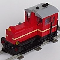
Lok24 Posted September 13, 2015 Posted September 13, 2015 (edited) Hi all, recently I presented remote decoupling in a separate wagon, today I want show a locomotive with the complete mechanism. Link to a short video (1min) The engine itself is very simple, basesd on the set-60098 Heavy Haul Train. I wanted the complete technical stuff to fit into a locomotive with the Lego-standard dimensions, that is 6wide, 32 studs long and 10 bricks high, span of the bogie centers is 18 studs. on the left: PF train motor, receiver and battery box in the middle upright: the motor for the decoupler on the right: gear for the decoupling mechanism The standard bottom plate (2 plates high) could not beused since the right bogie builds quite high. Therefore, stringers were used over the entire locomotive length. The force is transmitted via a bevel gear on a pinion which moves the rack in the bogie with the magnetic coupling. The problem: the way of the rack must be limited, otherwise the motor rotates the whole bogie. Given below is no space, the stop is installed above. yellow: drive from the motor to the clutch (which could be much easier with more space) green to bottom: the output of the slipping clutch down on the bevel gear and thus to the toothed rack with the coupling green to right: moving a vertical axis upwards with a 1x2 Liftarm as a stop (blue arrow) The bogie alone, the support removed. On this support the entire chassis is hold up, the connection is made only by the drive axle (in the picture above the four red arrows). The construction is based on an idea by Thomas Selander, presented in Railbricks. 13 Perhaps this is suggestion to try it, it really works fine, as I showed on the last exhibition in august. cu Lok 24 Edited September 13, 2015 by Lok24 Quote
Dread Pirate Rob Posted September 13, 2015 Posted September 13, 2015 Beautifully elegant. And I love that you not only got it into old school 6 wide, you used some classic buffers too. One question; is the clutch essential? I'd like to have a go at this but I'll have to make it lower profile. If you have time to do a video I would love to see this in action. Quote
Lok24 Posted September 13, 2015 Author Posted September 13, 2015 (edited) Hi Rob, oooops!! I forgot to post the link (now I edited the original post), but of course, here's the video (1 min.)! It does work without it, but if you dont stop, the motor will - at the end of the rack - turn the complete bogie! That's what the stop (1x2 liftarm upper right) is for. And without the clutch the motor still gives much power to the complete construction and might damage it. cu Lok 24 Edited September 13, 2015 by Lok24 Quote
AlmightyArjen Posted September 13, 2015 Posted September 13, 2015 Wow, that's really cool! Nice work! Quote
dr_spock Posted September 13, 2015 Posted September 13, 2015 Good work. Does it also work uncoupling on curved tracks? Quote
paul_delahaye Posted September 13, 2015 Posted September 13, 2015 Now that is a smart bit of engineering, nice job. Quote
LEGO Train 12 Volts Posted September 14, 2015 Posted September 14, 2015 Very complex mechanism! I like the use of the clutch gear! Amazing work! :wub; Quote
Lok24 Posted September 15, 2015 Author Posted September 15, 2015 (edited) Hi dr_spock, Does it also work uncoupling on curved tracks? Yes, sure. Perhaps it might be different on a left/right combination, which you have behind a switch point, but normal curved tracks are no problem. The mechanism isn't that complex as it looks like. Start with the bogie with the two racks, two gears and the support with the technic plate with holes, as shown in the last picture. Add 4 wheels. The technic bricks to hold the wheels are connected below with a plate 4 wide with 2 wide tiles on, on this support the coupler is moving. Then you build a plate for the PF-train-motor - again with the technic plate with holes - , app. 2/3 of the length of the loco, add some bricks to reach the height of the support of the bogie, and then add a technic plate with holes to sit on the bogie support. Then you combine “loco” and “bogie with an axle, the lower bevel gear and the clutch. Use same other parts to stabilize the whole construction Then it should run on the track and if you turn the clutch the decoupling mechanism is moved. Put the motor for that somewhere and connect to the clutch (not the axle, of course). With remote control with the wheels you can easily test. Last you have to attach the stop for the vertical axle, choose an appropriate low gear to satisfy the way the coupler has to move. That’s all, as you can see you can build the construction in several steps and find your own best choice for the components, as each engine is different. cu Lok24 Edited September 15, 2015 by Lok24 Quote
Man with a hat Posted September 16, 2015 Posted September 16, 2015 Very nice and elegant decoupling. Quote
cgarison Posted September 16, 2015 Posted September 16, 2015 Very nice work. This is much better than the push rod to separate trains that I have seen on a few displays. Quote
zephyr1934 Posted September 17, 2015 Posted September 17, 2015 Oh wow, that is a fantastic mechanism. Simple, direct and efficient. Great build... though looking at some of your other youtube videos this one looks simple compared to your factory and trolley bus. Please post more about your other creations too. Quote
baard Posted September 17, 2015 Posted September 17, 2015 Nice work! I like the way you have used the clutch gear. I developed Selander's technique by using a small linear actuator that could also fit in a bogie, this works like a charm too, and allow for even smaller locos to use the mechanism of a retracting magnet. See my flickr Keep ut the good work! Quote
Lok24 Posted September 18, 2015 Author Posted September 18, 2015 Hi all, though looking at some of your other youtube videos this one looks simple compared to your factory and trolley bus. Please post more about your other creations too. I presented them and different others here, and new ones will be presented in the future. Nice work! I developed Selander's technique by using a small linear actuator that could also fit in a bogie, this works like a charm too, and allow for even smaller locos to use the mechanism of a retracting magnet. My intention was to develop a solution for all wagons. My experience was, that even with the big linear actuator the way (and therefore the distance between loco magnet and wagon) is to small, if the wagon has steel axles. They are running that smooth that, if you drive the loco very slowly, they are following by the distant magnetic field only. As I have no layout my work is more experimental and should give ideas to others to try some "new" things. By the way, I've seen the pictures of your layout, that's really brilliant. cu lok24 Quote
Selander Posted September 19, 2015 Posted September 19, 2015 Impressive work ! Nice to see further ideas and development in this area which I find so interesting. Also many thanks for your kind recognition of my earlier work in this field. I currently use a version similar like Baard's in my Swedish T44 diesel and think it works alright. But I see your point of making a decoupler with longer stroke. Thanks again and I like to see more if your brilliant designs. PS: How do you like my version of your amazing V100 ? DS Quote
Lok24 Posted October 3, 2015 Author Posted October 3, 2015 (edited) Thomas, here's a little video ( 32 sec) It shows a wagon with steel axles and what happens if you have an offset of 3 studs and 5 studs. Of course, I agree to you, this effect takes place with light wagons and very slow acceleration only. Therefore I see that your linear actuator is very useful. Saw your V100, good idea to shorten the cabin to 6 to use the windows with frame. Nice work cu Lok 24 Edited October 3, 2015 by Lok24 Quote
Recommended Posts
Join the conversation
You can post now and register later. If you have an account, sign in now to post with your account.