

Gunners TekZone
-
Posts
178 -
Joined
3 Followers


About Gunners TekZone

Recent Profile Visitors
2,859 profile views

-
 Ah, sorry, I had missed that (and probably many other) details during my groggy reading stages
 -
Yes, I understood they can blindly all work the same. But was wondering if they could be (eventually if not already) recognised and controlled individually in Blocky... Hence my roundabout query to @Bliss However, I don't think he is able to look into this with only one RCX in his possession... So I will not worry about it myself... I am just testing for the moment as I do not have a "real world" case to use this at the moment. Alas... Too many other projects on back burners. And anyhow, making a nicely complex setup is beyond my mental/physical focus For now.
-
Yes. AFAIK this was normal operation with other programs (it is with the IR Remote Control). @BlissI did attempt to try a IF X OR Y input routine, to see if the RCX inputs act the same... But the RCX input block (or at least what looks like the closest match) will NOT connect??
-
Once I removed the RCX1 Alive? constraints, then YES multiple RCX bricks DO work (So far three of them, 2x 1.0 and 1x 2.0, all working as one)... At least as for testing outputs only (I haven't tested inputs yet, but probably the same). As for gain, well perhaps when needing to do many of the same thing. Eg. multiple track switching, lighting, etc or other motorized applications where one brick is not close enough (and without resorting to long leeds), or doesn't have enough needed outputs? Or a form of simple choreographed dance with multiple little yellow wheeled "bugs" on the floor I duno... I just like options (Granted, the IR tower range and angle becomes the limitation)
-
I have been keeping my testing simple lately... As I was making other things, and needed to recoup from that energy expenditure. So this time I am sticking with a single Int-A and an RCX Serial tower. Here are some observations... - No "Save As" option. I must remember to change the name of my saved program after the fact. - A saved program doesn't retain and reconnect device connections... This one had me doing a bunch of troubleshooting before realising that all the device allocations in my test program were listed "No RCX" and "No Lego B", thus requiring the manual reconnection and assignment of all devices in the program. Or doing such device connection (presumably in correct order?) prior to reloading a saved program. - On a wim, I tried having two RCX's online at the same time... Half expecting them to just be recognised as a single unit (for simple in-coming commands at least). But as soon as I turn the 2nd one on, the program stops running, and will not restart without turning off (any one) of the "extra" RCX bricks. Now, I was using the "While Rcx1 alive?" loop, so that might be a factor? I am guessing that in order to have multiple RCX bricks running, one needs a dedicated IR tower for each? It has been a long time since I messed with these little yellow bricks, but I thought these had some form of internal ID and could run multiples on a single tower?
-
No. But the proof of such is in the 'pudding' (AKA my 8 pin inverted swap worked ) Again, it was ONLY the eight pins 6, 8, 10, 12, 14, 18 & 20. on that connector that were "wired" as incorrectly inverted, TOP to BOTTOM in relation to the 6522's PB0-PB8. Flipping the whole connector Horz or Vert would NOT have fixed anything, but also messed up the 5v pin positions. Consider that on the "faulty" schematic, the order of a single pin from the Apple slot, through the 74LS245 to the 6522, and then to the ribbon connector is a set of flip-flopping (HIGH/LOW) pin designation inversions... Probably to keep IC placement and trace runs clean. The address for the Int-A Output Port 0: D1(Apple) to B7/A7 (74LS245) to D0/PB0 (6522) to Pin 20 (Input 7 on Ribbon connector). (the Red/Green colours represent the Input/Output Int-A LEDs) This last step shouldn't have been inverted, but the author might have just gone with the flip-flop flow. The correct last step is D0/PB0 (6522) to Pin 6 (Output 0 on Ribbon connector)... And so on for the remaining pins. I didn't realise it at the time (groggy eyes get crossed ) but there is another schematic, that is also on Evans website, that shows this correct layout. And hey, if someone posts a PCB layout back in 2019 and NO ONE seemed to notice and/or make a clear indication of it being in error (at least not on the forum I found it on)... Then how was I to know? This is me trying to make that PSA for others
-
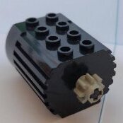
No apologies required. Solving (or re-solving) issues is a great way to learn, and I am finding it more beneficial to my clarity of thought then I would have suspected. The PCB was simply laid out wrong in this one area of the header, as every other pin is correct in all orientations. Here is my "corrected" version of the "problematic" schematic that I think the Reboot PCB was modeled after... I hope I got it right Unfortunately, I am not well-versed (or even poorly -versed) in the art of CAD/PCB design and layout, so I can't make a corrected PCB (maybe one day... Look out $$$ Blocky). Meanwhile, now I have two cards active, one for the "Apple IIe's" Interface-A and the other to mess around with alternate interface programming. Here I have the 2nd one with all 8 ports set to output (using 3mm LEDs with built-in resistors, just jammed into the ribbon cable for expediency ) So as to display the 8-bit binary output of an input number. Super simple stuff, but great to confirm code and pin orientation. And makes a good Larson Scanner I also realised there is nothing preventing these two cards from controlling a totally customised LEGO interface with any combination of inputs and outputs. It is just opto-isolators and H-bridges. Requiring custom code of course. But think about it, one 16 port 4.5v compatible (or even 12v for trains!!) LEGOlike Interface-DIY (Patent Pending ) perhaps with 6 inputs and running 5 motors, etc... Options!
-
The "irony"... In my attempt to avoid point to point soldering, I opted for the Reboot PCB option. And ended up doing exactly that anyhow to fix this boards' "issue". I can run, but I can't hide. Turns out even that repair was super simple... Although I continue to give GOD the glory for clearing the brain fog and for the insight, as was required to get this far. Here is a nice closeup for anyone wanting to do the same, but don't forget to cut the equivalent traces along that top row of the VIA (on both sides of PCB).
-
Ah, yes... that would make more sense. Perhaps "fair" in the sense of a niche product for a slim audience... But in no way for what it is component and (lack of) complexity wise. These Apple and IBM Interface cards are very simplistic in that sense. Welcome!! Join the club... Well, I guess I am the one joining the "clone" club. - APCO Apple IIe clone that needed minor trace repairs (With Floppy Drive, and a green phosphor monitor that needs a new case) - 2X "bodged to work" LEGO 9767 (reboot) cards. - And a 2nd Interface-A (boxed with OG cable and PSU). But all together, I still purchased all three for about the same $$$ as a single Blocko card!
-
What cards??? This was just made by PCBWay based directly on a design by David M back in 2019 and posted on the Applefritter forum. Perhaps he followed the tracing of such? If so I find it odd no one else used, noticed and commented about this issue (in his layout) since. But then it is a niche but loyal market I have messaged him already about issue and fix. Oh well... Now I know and the fix (for mine at least) is a simple bodge, no need to mod a cable that must follow those cards around forever.. Unfortunately, all too ridiculously pricey for what they are. I am in about $60 CAD for two, and three more boards that I might source out VIAs for... In case I want to follow in your footsteps and use ALL the interface-A's However, I think you are the king there
-
Earlier I had tested with LEGO original and standard ribbon cables. But as you should be able to see in 2nd photo, it is only the 8 data wires that needed to be flipped along the long axis to "fix" it, so issue resides on the PCB, somehow. One would have to compare the traces with an original card to confirm.
-
I used the original cable (70412) that came with my newest Interface-A (not the one pictured, as I was swapping them around to test), and had considered that it was flipped or backwards... But by its design that would have probably put all grounds to the data pins, and put the 5v and GND on totally wrong pins. However, I was right in my observation... Somehow this PCB is reversing JUST the 8 data lines. I took some dupont wires for 5V & GND and Ports 0-7, but I reverse the port wires on the interface (Pin 6 on the PCB to Pin 20 on the Int-A... Pin 20 on the PCB to Pin 6 on the Int-A... and so on). Works as it should now!! Go fig!?! Now I can either mod a specific cable for Apple use only... Or (more likely) cut 8 traces and bodge 8 wires on the PCB to reverse the 6522 PBx lines to the appropriate ribbon cable connector pins. What a bother But now I know I can successfully run an Interface-A (or two) on my APCO Apple IIe clone
-
Hmm... looking at it I was starting to see the pattern... What the interface should be seeing: IN OUT 7 6 5 4 3 2 1 What it seems to be seeing: with the Inputs always TRUE and Ports 1 & 2 always HIGH IN OUT 1 2 3 4 5 6 7 Somehow the card is sending inverted bits to the interface!! But so far I can't see how... I have been tracing the lines and ribbon cable and everything seems correct, granted all I have is the schematic this PCB is modeled on.
-
Yes, both are SY6522A from the larger of those two IO cards I had. But I also swapped in a MOS-6522 from a VIC-20 and it is the same. So either these older VIAs dont work quite the way the "newer" support ICs (and possibly the schematic wiring) are expecting?? I can find a W65C22N6TPG-14 on Mouser (seems to be the closest "newer" VIA to the one listed on the schematic)... But at about $50 CAD, I am not planning on getting one, on just a wim.
-
I suspect LEGO TC Logo does that (and I did set it for the correct slot I am using #2), as it will control four of the ports (2, 3, 4 , 5) if I use their "opposite" numbers. Eg: #5 for port 2. Same results with BASIC. I can POKE the values 4, 8, 16, 32 to toggle port 5, 4, 3, 2 respectively.