

Gunners TekZone
-
Posts
217 -
Joined
3 Followers


About Gunners TekZone

Recent Profile Visitors
3,350 profile views

-
 OK, I don't know why I never considered this before... But this thing (the three I have are the older LMS-ESP32-v1.0. Same, same) can already "control" an Interface-A and other components, as it has plenty of GPIO pins available. Just need a logic level converter or resistor dividers for the inputs. And I think 3.3v will trigger the Int-A outputs just fine. Hmm, controlling an Int-A from Technic HUBs!! OK, now I need to add that to my "Control Int-A via Sharp PC-G850" to-do list
 -
Anton's Mindstorms offers these technic connection points on their electronic add-ons. Makes for a very easy way to integrate into LEGO designs. (Just look beyond the fact that there is no Int-A involved here )
-
@Mr Hobbles Very Nice! Nice to se a clean compact adapter that can do LOGO, Python, PF... I like the little touch of making the board physically interfaceable as well. Does the IR run separately? As in just IR, just the cable or both? In case one doesn't want to blast IR out to unrelated PF devices in the vicinity. If you want to sell off a couple of those 1st batch, let me know in DM (I is in Canaderpia). You don't even need to "fix" them 1st as I can handle a soldering iron (well depending on which end I grab first).
-
Wow, that is some crazy pricing there (and opportunistic at $29 CAD each from the seller with 11 of them)... I am glad I grabbed the three I did back in May. I believe I got them for about $6 CAD each, and while they are the only ones I have, they made my Interface-A's 4.5v "collection" complete.
-
YES, as is just manual. NO LEGO program (although some simple "ladder logic?" like LEGO Lines could be programmed in) and YES same one on LVL1.
-
Oh wow! Very nice!! Makes me want to build something similar to fit in my current MEGA with display sandwich (it is already three boards thick including MEGA and display), to add in the Blockly BT option, and a nicer Int-A connection with less dupont. As well as just for the fun of building it Alas... First I still need to find a way to merge the MEGA Touch Screen control and Blockly interface code together... And catch up with all the Blockly changes... But all that requires too much thinking So for now I just lurk BTW... I have noticed that both of my Interface-A's only output 3.7 - 3.8vdc (but it is stable even with motors running) regardless of type of AC or DC adapter connected to them. Can others measure their voltage outputs and let me know what they are? Thanks! I am wondering if I need to do some regulator upgrades in both of mine??
-
This LVL1 Website might have already been referenced somewhere deep in this "Control Interface-A with Everything" topic? But here it is again. And it is working very well. The touchscreen is a nice "touch" Alas, it is not "programmable"... But I think I might take a stab at modifying its sketch to "hopefully" allow this interface to still respond to touch and control the Int-A as it does, but also display and pass on the Inputs and Outputs generated by running code from @Bliss's Blockly development, in place of the NANO that I have already tested to successfully do that. And here is a short video link of it in action, that I will try to keep around as long as I have space in my Public Dropbox. https://www.dropbox.com/scl/fi/zdk8iptij91zfb25rz5ut/20260410_222147.mp4?rlkey=0whm0j6oniyrun05ws93u67wr&dl=1
-
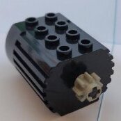
Ha... Same question @evank asked when he saw a pic... Yes, the Interface-A only puts out 4.5v so the 9v motors run a bit slower. But as they are internally geared, they still run with more torque (and plenty fast enough) than the 4.5v motors with a bunch of LEGO gearing added. Oh, and as the wires for the 9v cables tend to rot, I learned how to make my own cables. I originally tried this, but was crazy slow, and still too weak.
-
Um... What? Can't there be a simple LOOP While COUNT INP (6) < (10) and/or LOOP Until COUNT INP (6) (=>) (10) block? (Stuff in brackets can be adjusted) That starts from 0 and internally counts up (via input state change)?
-
This is a video of Blockly via Arduino Nano, to LEGO DACTA Interface-A, to a little robot arm simulating a welding machine (Unfortunately the old white friction gears in the arm often damp down what was to be more dramatic movements). NOTE: This link will not stay valid forever https://www.dropbox.com/scl/fi/szpsacoz89awqiy3bo5v6/20260408_190056.mp4?rlkey=18l0c233zk9lkzyn54z2wcnh9&dl=1
-
I did Ctrl+Shift+R to refresh... And fooey, I should have listened to that little voice and saved first Anyhow, I had my screenshot to quickly fall back on what changes I had made... Only this time I didn't bother commenting and "cleaning" up unused code... I just broke the connection where I wanted to to end... Which apparently DOES NOT actually break the flow??? Wow... Note to self... Leaving "scraps" of blocks around might affect how the code runs. Anyhow, YES! that adjustment to the input value worked!... And apparently so does the rest of your code ... Albeit the count times are dramatically shorter than they should be. Oh, goody... There is still something to figure out Doubling the count brought it to the expected LL results. Granted, those old friction gears I need to use in the arms are so inaccurate that precision positioning is not possible. So, I am guessing you setup is counting either ON or OFF states, not the transition between states?
-
OK... This little startup process works, right up until the limit switch. Which IS showing about 4v on the Arduino A0 pin (and on A1, as it happened to land just right on the rotation sensor as well). EDIT: I figured out how to show the Input 6 value... Hmm, perhaps 888 isn't enough to trigger as ON? Odd values, as the switch I am now using is the original 4.5v one that is simple ON/OFF... With no option for any "pressure variance". Perhaps, since the Int-A inputs do not seem to offer much in "range", the Arduino should just use a GPIO and not an Analog pin? That might make any counting (if I can figure out that part) much more reliable as well.
-
No... I have a bad memory for using KB/mouse combo keys... I just click and drag This is what I mean. I need to see a bigger picture to figure out something in a flow... But with blocks, it gets too small as to be readable for me BUT finally I was able to "see" it... Oh my goodness, there is a Sub Routine at the end that makes the UpdateOutputs block work!! And here I was thinking this was just a progression of blocks going from top down and wrap back up to top right and down again, etc. (as in writing text in three columns). So every time I erased the last part, it messed up those blocks. And for some reason undo didn't bring that group of code back.
-
@Bliss ARGGG... OK, using your long version of my LL code, I just isolated the beginning routine (adjusted to work) showing how I set and moved my arm with one end stop input and one optical rotation input. And realised that the end stop wasn't stopping the code?!?! (I didn't notice on the robot as the motors simply stalled quietly) and thus never got to the counting part. However, as I was trying to arrange a screenshot (and getting rid of non-relevant blocks, to clear the screen and my mind)... It somehow it mixed up and/or erased (again) the relevant code that I had scrolled away from to get at the rest. And whatever Undo does is well, not what is expected (placed random blocks and comments in odd locations)... And only seems limited to one or two steps back? Bah! And the method of grabbing a group of blocks (no rubber banding?) still confounds me as to where to grab what to do what I expect. Again, Bah... I do NOT like block programming. Another coffee... And then I might try again with something even simpler from scratch, to determine if the sensors are working as I thought they were
-
Yes, Python part is totally free. The Block part starts at $7.50 CA / month or $79.00 CA for life (perpetual licence). I think I tested the block side once or twice when it was free... And hated it... And have since only ever used their Python side. OK, I am embarrassed to say that I didn't catch on about Blockly being a Google project Now some of @Toastie's comments/questions make more sense.. Doh! Carry on as you were Ah, JavaScript... Yes I learned me a bit of that in Node-Red... The only graphical programming style my mind seemed to be able to work around. Possibly due their more "free" range layouts joined by connecting "wires" conforms to electrical breadboarding? As opposed to Blocks "magnetic" snap (that always confounds me to get correct) and generally vertical progression.