

Bartholomew
-
Posts
25 -
Joined
-
Last visited
Content Type
Profiles
Forums
Gallery
Everything posted by Bartholomew
-
That was the solution used in the prototype seen at Nuremberg toy fair.
-
Seems like with a single 16t cog, one can drive one of the PTOs and the compressor at the same time (if you want to). It's obvious in the last picture of the review. Sounds great :) And another test idea: How much grade/slope can the Unimog handle using its winch?
-
Nice video :) Can the crane load the demounted winch from the ground into the dump bed? I also wonder if the turning radius could be reduced by removing/replacing the dark-bley 1,5L pins. There were similar parts that combined a 1l pin and a stud in the past (light grey) that were slightly less long than these, aren't those produced anymore?
-
It's a Panhard rod, a Watt's linkage is more complicated. Whe had that sorted out one page back ;-) http://en.wikipedia.org/wiki/Panhard_rod http://en.wikipedia.org/wiki/Watt%27s_linkage And thanks for all that material
-
@gjpauler: I can't access your photos. Maybe you can upload them at brickshelf.com , too?
-
Yes, but you have to switch channels and can't use all 8 channels at the same time, just 4 simultaneously.
-
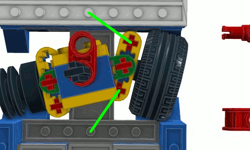
Thanks for the correction :) Yes, two diagonally mounted panhard rod, one for each axle. In the marked picture, I got the perspective all wrong... In these pics, all is visible more clearly:
-
You've omitted a "not", Gerhard ;-) Don't these rods/beams stiffen the mounting suspension of each axis in a way that permits wide contraction of both shock absorbers at the same time? There are two of them on the front axle too, iirc.

-
Rubber bands could do the trick.
-
My impression is that the new black "rim connector" (or how it is called) is slightly different to the old one, then. One can see that the slits on the three rim pegs are now circular, not radial anymore. As soon as the axle is inserted in the central peg, you cannot part rim connector and portal axle housing anymore, because the central peg can't compress anymore -> sturdy design. At least, that's my guess. I know the old black rim connector from photos only
-
Will be another symmetrical red bushing at the back side. One can see it through the gap in the 3L u-joint, that's why it looks like a small circle. This setup was needed to get the housing as small as possible (pivot point). Doesn't look like Ackermann steering to me, the front wheels seem to be parallel at any time. Yes, one can see the two clips of the central axle left to the lower 16 teeth cogwheel in the cgi, inside the bley portal axle housing.
-
I've measured it. In the above rendered picture, the 16 teeth gear has a radius of 40 pixel, so a 24 teeth gear would have 60 pixel. The available space seems to be 61 pixel. So yes, it will match inside. It would be kind of dumb from TLC not to make this possible, imho. P.S.: For the Linux users out there: "kruler" is sometimes quite handy :)
-
Centrifugal Tachometer
Bartholomew replied to nico71's topic in LEGO Technic, Mindstorms, Model Team and Scale Modeling
Nope, centrifugal governors were used in mills long before they were used in steam engines. By the way, James Watt did not even invent the steam engine He improved it and made it usable for industrial purposes, and casually introduced the unit "horsepower" to show potential customers how strong his machines were. But before him there were Blasco de Garay 1543, Denis Papin 1690, Thomas Savery 1698 and finally Thomas Newcomen 1712. Same with Edison and the light bulb, which was not invented by him, but improved to marketability, and that's what he is credited for. Anyway, I like your version more, because it is more solid an very usable for educational purpose. -
MOC: Case Steiger 335
Bartholomew replied to dhc6twinotter's topic in LEGO Technic, Mindstorms, Model Team and Scale Modeling
Your video says 7. Anyway, quite impressive and a job well done -
Although it violates Kepler's laws in a way that it does not earn it's name, it is nice to watch.
-
Driving direction of the Unimog an rotating direction of the PTOs would be coupled this way. Switching the direction of the motor (and the things it drives) will be done by the switch on the battery box. Also, that M-motor would be too weak do drive the vehicle, the compressor and a PTO simultaneously. TLC does not want children to overload the M-motor unwittingly, so compressor and PTO can't be driven simultaneously (imho). So, the battery box switch will define the PTO direction, the yellow switch will couple the motor with either compressor or PTO-drivechain, the red switch will direct power either to the front or the rear PTO, and the pneumatic valve will direct air either to the front or the rear air outlet. Finally, automobiles that drive away from you because you don't hold the remote controls for it in your hand are no fun for children (who will stall the motor by holding the vehicle) and for TLC (because of angry parents)
-
Or they just don't give pictures away to non-press people.
-
Durability tip: Do never deplete your rechargeable batteries completely, this will damage them. In fact, one should stop when voltage drops below approx. 1V per cell (Ni-CD and Ni-MH; one will notice a performance drop also). Some cells contain less energy than others, these will be first depleted. If these cells are kept in use, current will flow "the wrong way" through these depleted cells: They should now be recharged, but instead get even more used up by the wrong current. So, if you like your rechargeable batteries, change them in time :)
-
As long as the motors don't stall, it's all right.
-
This loop has a meaning. It was made by a greater force that wanted us to finally catch the fact that the headlight below the right exterior mirror was attached in a wrong way
-
So, that thingy will be around 64cm long, 36cm high and 27cm wide, without add-ons. Nice. Compared to the Nuremberg Toy Fair model, they seem to have altered the way of the tubing a bit: The pump seems to be 180° rotated, and of course the front outlet is different. By the way: Was the 1/2L pulley/bushing available in yellow before? It's just left of the exhaust, next to the little yellow beam: http://storage.technicbricks.com/Media/2011/TBs_20110207_1/TBs_20110207_1d.jpg In that picture, you can also see how the tubing was connected to the pump before. Edit: Unlikely, I can't see a switch for that; neither has the bed working hatches. But it would be a nice project to remake the 8110 to the longer U 400 version and integrate a sideway-dumping mechanism (dumping to the back with mounted rear add-on wouldn't make much sense).
-
Thanks for the correction, Philo, and generally for your great site :) I still have problems disassembling my battery box (there will be some catches that bother me), but since there are schematics on your site, I don't have to anymore. Also kudos to Blakbirk for his Technicopedia. I'm looking forward to the 1996 update :)
-
@Superkalle: Nice pictures :) @David Luders: No, I deduced what I wrote about the C1/C2-Lines from what i had read at Philos site, without testing things myself. Meanwhile, i've made a resistance measurment of the 0V/9V-contacts from an PF medium motor - they are not connected to anything in the motor. So, in the sketch with the blue and red wiring you've embedded in your post, dashed lines definitely means unused lines (but they're still looped through to the connector terminals to allow easy daisy chaining). I've done some further measuring on my 8043. The results: 6 cells: Standby current drain of LED in PF battery box: 5,8mA Standby current drain of single IR receiver (computed): 14,5mA Total standby current: 34,8mA Standby voltage (35mA): 7.85V Motor with minimal load (clutch in neutral position): 75-85mA Motor with little load (Bucket): ~130mA Motor with heavy load (lifitng jib): ~330mA Stalling motor: ~620mA ~7,37V Two stalling motors: ~1080mA ~7,05V Three stalling motors: ~1500mA ~6,83V Four stalling motors: ~1800mA 6,54V With rising current, the battery voltage drops, and so four stalling motors don't drain 4*620mA=2480mA, but 1800mA. If a stalling motor is kept powered, the current drops due to motor-internal protection electronic (the PTC gets warm and rises its internal resistance). If I stall all four motors and keep them powered, the IR receiver overcurrent protection kicks in, resulting in cyclic contraction and relaxation of the separate geartrains. This does not happen at lower currents, i.e. if I reduce the number of stalled motors to three, or the total cells (and such the voltage and indirectly the current) used. As not all motors relax together, I know this effect comes from the receivers and not from the battery box. Four cells: Total standby current: 20mA 5,14V Motor with minimal load (clutch in neutral position): 65mA Motor with little load (Bucket): ~120mA Motor with heavy load (lifitng jib): ~250mA Stalling motor: ~410mA Three cells: Total standby current: 11mA 3,85V Motor with minimal load (clutch in neutral position): 60mA Motor with little load (Bucket): ~110mA (slow) Motor with heavy load (lifitng jib): ~220mA (very slow) Stalling motor: ~315mA Two cells: Total standby current: 2mA 2,57V Motor with minimal load (clutch in neutral position): 47mA Motor with little load (Bucket): ~80mA (slow) Motor with heavy load (lifitng jib): stalls Stalling motor: ~210mA One cell: Total standby current: 0mA 1,28V Not enough voltage for battery box LED (will need about 1,7V), nor for the IR reveivers.
-
Thank you :) Testing is complete. I used my 8043 excavator which comes with the standard PF battery box that roamingstudio linked. In order to short the contacts, I first insulated both poles of fresh alkaline cells with adhesive tape, then wrapped the cells in metallised paper from chewing gums (and I didn't even watch that much McGyver when I was young :D ). Result: Works like a charm :) Less speed, less noise, less torque with every cell wrapped in chewing gum paper. I stopped with four bridged compartments, because I ran out of gum (and the IR receivers are not likely to work with 1,2V remainig voltage anyway, as I use Eneloop rechargeable cells). If the motor has problems turning the rotor because of lack of torque, I recommend using a cell more to prevent stalling. I do think that even at lower voltage a stalling motor can overheat and thus be permanently damaged, but I'm not sure since I haven't measured the corresponding current yet. I can't open the battery box (momentary lack of matching screwdrivers as prying tools) to check if there is any kind of overcurrent protection installed, maybe I catch that up next saturday. P.S.: be carefull not to accidentially short two neigbouring compartments, as you could short a working cell this way if vou've got an unlucky alignment of working cells and shortened cells. Iv you've got a continuity tester, you can simply check the wiring of your battery box to avoid this (but if you own such a tool, you know that anyway).
-
Hi folks, I'm new :) First of all: Nice place here, I feel comfortable. Second: I'm a native German speaker, so please be patient if i use strange words when explaning something. Corrections are strongly approved! @roamingstudio: You've linked the 6*AA battery box. If I interpret Philo's figures Philo right, then that won't work. I do think the motors take their power completely from C1 and C2, and totally ignore the 0V and 9V lines, as the LEDs do (I'm sure about them, as there are schematics at Philo's site). I do think that you mean that the motors have integrated driving transistors. This theoretically possible design brings no advancements compared to the driver-transistors-in-control-element-solution, and so Mr Ockham says it's not very likely. I think that normal PF speed and direction control works via pulse width modulation. That means that C1 and C2 are electronically connected to 0V and 9V for a short time x and then turned off for another short time y, whereby x+y=T is constant, and will be around 1/20000 s. For direction change, C1 and C2 can be electronically or mechanically toggled (can one say "commuted" in this context?). So, if the battery box has no electronic that won't work with the lower voltage you get when you use less than six cells, reducing the motor speed this way will work. A trial surely won't damage any parts. But do not simply wrap old used-up cells in aluminium foil and short the contacts this way, because used-up alkaline cells tend to leak (this is also the main reason why you shouldn't use cells of different type or age in the same battery box, because the one used up first has an increased risk of leaking while the other cells keep on pumping current through it). I've read the newer battery boxes have a safety current limitation, not the motors. The old motors had a (P)PTC (those are current sensitive, not voltage sensitive), and i dont't think they've changed that in the new motors.