
PlanetaryHub
-
Posts
20 -
Joined
-
Last visited
Content Type
Profiles
Forums
Gallery
Everything posted by PlanetaryHub
-
 Last "Easter Holidays" video just posted on YouTube - enjoy:
 -
@deraven Thanks. I guess, if Lego have no official name, it can be referred to as the "Ø1.5mm shaft & socket connector system" without confusion?
-
Driving the planetary hub directly with an XL motor does give a lot of torque due to the 3:1 step down. As you suggest a slightly larger scale model (longer track) would probably be better - the video was just intended to be fun.
-
New track test rig video just uploaded to YouTube:
-
Please could someone tell me what the correct Lego terminology is for the cylindrical sockets and pins used to attach mini figure accessories, for example a feather to a crown: Thanks.
-
@Dafgek81 Thanks for your interest, I will keep you posted - another video is on the way and will be uploaded shortly... @JJ2 Thanks for your feedback, one solution is to add a hub cover:
-
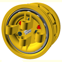
Yes, on real world parts the hub internals are hidden by a cover that forms part of the rim assembly. However with these parts I was keen to maximise their educational value and therefore decided to leave the planet carrier exposed and also provide a good view of the gears in action by peppering it with holes! Nonetheless they are close in design to real world parts and work in an authentic way, this allows realistic functional models to be built.
-
A new video for your delectation...
-
Just for fun, while Shapewaiting, I have uploaded a short animated video of a track loop running on two planetary hubs: https://www.youtube.com/channel/UCRxfS08NGOt0pCMtIKLkLXg
-
Thanks for the information efferman! No, my CAD holes are circular
-
BrickWarriors Jan 2016 - New Steampunk Pieces!
PlanetaryHub replied to Thrash's topic in Minifig Customisation Workshop
I like the detail on the trench coat, very good. -
1) Is my CAD orientation correct: hole axis = z-axis? 2) I assume my CAD dimensions are OK...?
-
@efferman 1) How do you know which way up Shapeways will print an item? I had the impression that they rotated parts to optimise use of the printer's material box, i.e. packing as many parts in as possible with no guaranteed orientation...? 2) I have found the test part that I printed at Shapeways!: It is a 1M long version of the standard 2M Tube Coupler ( http://brickset.com/parts/4526985 ) and probably similar to the 1x1 Beam ( http://brickset.com/parts/6100030 ). The part's cylindrical axis is parallel to the z-axis in the stl file and it was printed in unpolished strong & flexible. LEGO axles will fit in the bore, but rotate with some friction. LEGO friction connector peg's will also go in, but are very tight. The dimensions compare as follows: [mm] CAD Actual Outside Diameter 7.80 7.76 Bore Diameter 4.90 4.75 Overall Length 7.80 7.96 Any thoughts on why the bore & overall length are not closer to the CAD dimensions? Thanks.
-
@efferman Thank you for your help. 1) Just to confirm that I have understood you: if I had an 8.0mm diameter rod, it would need to be in a 8.6mm diameter hole to rotate freely...? 2) Do you just use unpolished nylon? Is this to avoid the dimensions changing unpredictably during polishing? 3) Last year I did print off a small test part in nylon at Shapeways (added to an order for something else not LEGO related). The CAD file had a 4.9mm diameter hole, but the hole in the actual part was smaller. When I find the test part, I will post the actual dimensions. If this discussion is boring everyone else, I could revert to PM's - let me know.
-
@efferman Your Technic parts on Shapeways look great. Please can you help me with some advice on correct tolerancing for printing successfully in fused nylon (strong & flexible) at Shapeways?
-
...you are correct, so OK by LEGO :)
-
Thank you for all your thoughts and comments. If you like the parts and have not commented please do so, it could help win TLG over! Some specific replies: Dafgek81: Not sure it is a technique that LEGO would approve of, but yes I have also pushed a rod down the centre of Technic pegs, which keeps the ends splayed and thus stops them pulling out! Blakbird: I think plastic would be fine for the ball bearings in a production version. (Plastic balls made of materials such as Du Pont Delrin are used in some real world bearings; I am not suggesting that anything that sophisticated is needed here!) efferman: I feel that It would be best for everyone if TLG could be persuded to produce the parts in injection moulded ABS, so I would like to stick with that option at present. Clearly if there really is no hope of TLG listening and taking an interest :( , then I am happy to consider alternatives - I do not want to see my design "go to waste". If this is the case perhaps you could help me(?), but I really would like to stick with trying to get TLG to take an interest at present. Saberwing40k: I used OpenSCAD for model generation and rendering, it is freeware :) www.openscad.org SevenStuds: (please see reply to efferman above) Are there any other LUG forums I should post my request for help/support to? Any other ideas to gather more support? Thanks, I like this forum, you are all so helpful and friendly!
-
Practise Posting Here!
PlanetaryHub replied to Pandora's topic in New Member Section - PLEASE READ BEFORE STARTING!
Testing video inclusion: -ends- -
If I dare ask, any suggestions as to which other forums I should post this request for help on? - USA?
-
Thanks for all your kind words. In case you missed it on YouTube (the description text is not very obvious), the key design features are: 1) Planetary gear train built into a standard 56x34 rim - the gear train provides a 3:1 speed reduction and a corresponding 1:3 increase in torque. The output torque is generated at the internal gear and transmitted directly to the rim and from there to the tyre or track, therefore it does not pass through any axles. 2) Integrated 14 tooth track drive sprocket - increases potential applications, the rim flanges provide lateral support on the underside of the track segment plates. The sprocket is hidden when a tyre is fitted. 3) 4-point universal mount - this is designed to accommodate: rigid axle, rigid axle with steering, suspension or suspension with steering set-ups, all utilising standard components. The pivot point is positioned to allow the use of either a one part universal joint or a 2 part cardan joint. 4) Rolling element bearings - provide authenticity, tight rim location with little free play and also give low rolling resistance.
-
Hello, Having played extensively with LEGO Technic as a youth (I still have the original 853 Car Chassis Technical set), I now find myself playing with LEGO Technic with my son! I am a vehicle design engineer by trade and this combined with the time spent playing with LEGO Technic resulted in an idea for a new Technic compatible part. After this idea had knocked around in my mind for some time and refused to go away, I decided to design in properly using 3D CAD and present it to the Lego Group to see what they thought. I put together the following video and sent it by e-mail to the LEGO Group several months ago, but I have had no success in getting them to take an interest in the proposal: My design cannot be submitted through the LEGO Ideas web site, because new part designs are specifically excluded. However if I can get to at least 10,000 views on YouTube (the LEGO Ideas review threshold), I think LEGO Group may be prepared to give serious consideration to producing these new parts. If you like the idea please help by sharing this video on social media, in forums and with friends. Thank you for your help.
-
Practise Posting Here!
PlanetaryHub replied to Pandora's topic in New Member Section - PLEASE READ BEFORE STARTING!
Hello everyone, this is just a test message... message 2 blah blah! still testing!