[MOC] UCS CR-90 Corellian Corvette – Blockade Runner (Tantive IV)
The work building a Rebel Fleet continues!
The latest addition the Rebel Fleet is the CR-90 Corellian Corvette, better know as a Blockade Runner. The CR-90 was built by the Corellian Engineering Corporation for the Empire, but many of them were stolen by the Rebels. Over time they became a mainstay in the Rebel fleets. This specific rendition is of course Leia’s counselor ship: the Tantive IV.
The model is built using the same 2-meter/stud scale as the rest of my Rebel ships and fighters. Thus the 150-meter ship becomes a 75-stud model. My goal was, as always, to capture every little detail of the studio model. However, this time there was also the challenge to improve the two official renditions of the ship. Comparing the TLG versions with the studio model, it became clear that getting the proportions right seems to be difficult - since both version are pretty far off.
As always the design process began in LDD but ended in bricks – some things are simply more easily designed in real life :) When I was done the model consisted of just over 2800 bricks distributed across 250 brick types.
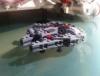
The Tantive IV.
Chased Through Space. This angle shows off the command section - which was one of the last parts I built. I knew all the proportions of the section; it was just a question of how I could represent them best while retaining crucial detail. It was tempting just to use large cone bricks. But I did not want to compromise any detail. I ended up using a lot of different slope -and wedge bricks and plates, combined with hinges and tiles. Dark red round 4 x 4 plates in combination with 3 x 3 discs was the solution for the red markings on the sides of the command structure. However, this also meant I had to make room for technic axles inside the cockpit – alongside hinges, the spine of the ship, and other stuff. Suffice to say, it is a very cramped bridge :)
Model Side View. As mentioned above, getting the proportions to fit with the studio model was a priority when designing the ship. Using pictures and diagrams of the studio model, I have gotten with within a pretty tiny margin.
Model Top View. Another challenge was to replicate the smooth transition from the body to the engines section. To achieve that I used corner slopes. Comparison pictures of the studio model can be found here:
http://www.modelermagic.com/?p=57848
The Main Dish. The mold for the main dish is the same as the one used on the two TLG versions of the ship. The way it is mounted is inspired by the movie version - using droid arms to get the proper detail.
Just below the dish, the studio model has two angled door-like vents on either side of the base. I have recreated this detail using hinges and grilles. On the same base, facing the engines, are also four small, horizontal cylinders – these are visible in the picture below.
The area around the antenna sports an almost fin-like structure. The purpose of this structure is to stabilize the otherwise very slender body of the ship – considering the combined torque provided by the 11 Girodyne Ter58 Ion Turbine Engines. I tried to convey this thin structure in a multitude of ways. The cleanest solution I found was using flags. Flags are quite thin and can be placed at the desired angle with no fuss. Using several flags in a row I could slightly adjust the angle from flag to flag to approximate the desired lines.
Docking Rings. Beneath the antenna we have the symmetrical docking area. Here we find the docking rings where the CR-90 can dock with other ships. An interesting side note: since the early concepts and prototype models of the Blockade Runner was referred to as the “smugglers ship” aka the Millennium Falcon, the round housings around the docking rings were originally supposed to represent a one floor walkway. The equivalent on the final Falcon is the side docking rings – in the Smuggler Ship’s original form these we 1:1 with the ones on the Falcon. In the final version of the Blockade Runner, the docking tubes are representing several floors of walkways.
In this picture it is also apparent that the ship if made up of a number of slightly different sized cylinders. To get these shapes I once again turned to the curved slopes I used in the GR-75. It turned that I could render most of the core body of the ship using these bricks – all I had to do was to create a long square 4x4 center with studs on all sides running through the entire body :)
The Main Turrets. As with the docking rings the main turrets were originally equivalent of the turrets seen on the Falcon. Since the ship changed purpose and scale substantially during production of “The Star Wars”, the turrets grew from anti-fighter duty, to heavy turrets effective against large ships – although still immensely underpowered against the shielding of an Imperial Star Destroyer :)
Main Hull. The main hull of the ship houses the living quarters. We also find a number of smaller anti-fighter turrets. Oddly these turrets are only found on the dorsal part of the ship, rendering it vulnerable to fighter attacks from the ventral angle. This part also sport a bit of discrete piping.
On the spine of the main hull is more detailing and I have displaced some of the slopes one plate to give the side of the spine some texture.
Escape pods. But who cares about fighter attacks or encroaching Star Destroyers, when you can jettison yourself to the desolate safety of Tatooine’s sand dunes? As you can see, several of the escape pods have already taken off – perhaps one of them were carrying a couple of oddball droids? The escape pods are made up of a 2x2 cone brick with a 1x1 round tile on top. Jettisoned escape pods are represented by a 2x2 round dbg tile with a hole in the middle, to convey the scorching from the explosion that shot the unlocked escape pod into space.
Side Detail. On the sides of the main hull there is a narrow band of greebling on the studio model. The band wraps around the entire section and, like with the section itself, I used hinge bricks to capture the different angles.
Main Turrets Bottom View. In this close-up we see more of the detailing of the main turrets. This area also hides the ship’s front landing legs – where the transparent stand is. However the ship is in flight right now so the legs have been retracted :)
Engines! Now to the best part of any ship :) The official UCS version (10019) of the Tantive IV was one of my favorite ships for a long time. But when seeing the movies, it is clear that the Lego version has some issues regarding proportions. It is very bulky and square looking and does not properly convey the slender nature of the ship. This is especially true for the engine section, which is a large square block with oversized engines placed directly next to each other. In this regard the later 10198 is much more accurate.
I my version the engines have the correct diameter and length in relation to the ship’s overall proportions. The horizontal spacing between the engines are ½ engine diameter. The vertical spacing between the three rows of engines are around half a stud. Each engine sports brick built panel with detailing – no stickers :). I used a bracket brick to have the panel run down the sides of the cylinder.
Engines Top View. The 11 Girodyne Ter58 Ion Turbine Engines in all their glory! Here you can see all the details and cables on the engines. I considered using rigid cables, but I had to heat them up to get the proper shape. The cables were also too thick. However, I found that by placing a 1x2 bracket in the side panels I could place levers on top of them. The levers convey thin cables running from the sides of the engine to its core.
Engines Close-up. The engine housings were also detailed looking at the studio model and as you can see not two engines are the same. It is worth noticing the angles of the engine housings. I have tried to get as close to the studio model as possible, while also taking into account that the side-most engines have a steeper angle. The middle (seen from the side) engine housings also have their own specific angle. These features were completely ignored on the official TLG models and contributed to the 10019’s blocky appearance.
Engines Bottom Rear View. As mentioned above, each engine is different. This is not only in terms of detailing, but also how they are attached to the ship. Top, middle and bottom engines are attached differently. Top engines are placed on the top of a plate, middle ones at the end of technic bricks, and bottom ones are attached to the bottom of plates. Since the engines are mirrored left/right not two engines are the exact same.
The detailing of the nozzle of the engines is made using a sailing ship rudder and a lot of 1x1plates with side clips and 1x1 tiles. And yes, the exhaust should have been yellow, but there are no trans-yellow 3x3 dishes :)
Scale Comparison. As always, I have a scale model with my MOCs. This time the model is my 7½-week-old son. He is a huge Lego Star Wars fan :)
The Tantive IV Flying Away.
Enjoy, and please comment!
The work building a Rebel Fleet continues!
The latest addition the Rebel Fleet is the CR-90 Corellian Corvette, better know as a Blockade Runner. The CR-90 was built by the Corellian Engineering Corporation for the Empire, but many of them were stolen by the Rebels. Over time they became a mainstay in the Rebel fleets. This specific rendition is of course Leia’s counselor ship: the Tantive IV.
The model is built using the same 2-meter/stud scale as the rest of my Rebel ships and fighters. Thus the 150-meter ship becomes a 75-stud model. My goal was, as always, to capture every little detail of the studio model. However, this time there was also the challenge to improve the two official renditions of the ship. Comparing the TLG versions with the studio model, it became clear that getting the proportions right seems to be difficult - since both version are pretty far off.
As always the design process began in LDD but ended in bricks – some things are simply more easily designed in real life :) When I was done the model consisted of just over 2800 bricks distributed across 250 brick types.
The Tantive IV.
Chased Through Space. This angle shows off the command section - which was one of the last parts I built. I knew all the proportions of the section; it was just a question of how I could represent them best while retaining crucial detail. It was tempting just to use large cone bricks. But I did not want to compromise any detail. I ended up using a lot of different slope -and wedge bricks and plates, combined with hinges and tiles. Dark red round 4 x 4 plates in combination with 3 x 3 discs was the solution for the red markings on the sides of the command structure. However, this also meant I had to make room for technic axles inside the cockpit – alongside hinges, the spine of the ship, and other stuff. Suffice to say, it is a very cramped bridge :)
Model Side View. As mentioned above, getting the proportions to fit with the studio model was a priority when designing the ship. Using pictures and diagrams of the studio model, I have gotten with within a pretty tiny margin.
Model Top View. Another challenge was to replicate the smooth transition from the body to the engines section. To achieve that I used corner slopes. Comparison pictures of the studio model can be found here:
http://www.modelermagic.com/?p=57848
The Main Dish. The mold for the main dish is the same as the one used on the two TLG versions of the ship. The way it is mounted is inspired by the movie version - using droid arms to get the proper detail.
Just below the dish, the studio model has two angled door-like vents on either side of the base. I have recreated this detail using hinges and grilles. On the same base, facing the engines, are also four small, horizontal cylinders – these are visible in the picture below.
The area around the antenna sports an almost fin-like structure. The purpose of this structure is to stabilize the otherwise very slender body of the ship – considering the combined torque provided by the 11 Girodyne Ter58 Ion Turbine Engines. I tried to convey this thin structure in a multitude of ways. The cleanest solution I found was using flags. Flags are quite thin and can be placed at the desired angle with no fuss. Using several flags in a row I could slightly adjust the angle from flag to flag to approximate the desired lines.
Docking Rings. Beneath the antenna we have the symmetrical docking area. Here we find the docking rings where the CR-90 can dock with other ships. An interesting side note: since the early concepts and prototype models of the Blockade Runner was referred to as the “smugglers ship” aka the Millennium Falcon, the round housings around the docking rings were originally supposed to represent a one floor walkway. The equivalent on the final Falcon is the side docking rings – in the Smuggler Ship’s original form these we 1:1 with the ones on the Falcon. In the final version of the Blockade Runner, the docking tubes are representing several floors of walkways.
In this picture it is also apparent that the ship if made up of a number of slightly different sized cylinders. To get these shapes I once again turned to the curved slopes I used in the GR-75. It turned that I could render most of the core body of the ship using these bricks – all I had to do was to create a long square 4x4 center with studs on all sides running through the entire body :)
The Main Turrets. As with the docking rings the main turrets were originally equivalent of the turrets seen on the Falcon. Since the ship changed purpose and scale substantially during production of “The Star Wars”, the turrets grew from anti-fighter duty, to heavy turrets effective against large ships – although still immensely underpowered against the shielding of an Imperial Star Destroyer :)
Main Hull. The main hull of the ship houses the living quarters. We also find a number of smaller anti-fighter turrets. Oddly these turrets are only found on the dorsal part of the ship, rendering it vulnerable to fighter attacks from the ventral angle. This part also sport a bit of discrete piping.
On the spine of the main hull is more detailing and I have displaced some of the slopes one plate to give the side of the spine some texture.
Escape pods. But who cares about fighter attacks or encroaching Star Destroyers, when you can jettison yourself to the desolate safety of Tatooine’s sand dunes? As you can see, several of the escape pods have already taken off – perhaps one of them were carrying a couple of oddball droids? The escape pods are made up of a 2x2 cone brick with a 1x1 round tile on top. Jettisoned escape pods are represented by a 2x2 round dbg tile with a hole in the middle, to convey the scorching from the explosion that shot the unlocked escape pod into space.
Side Detail. On the sides of the main hull there is a narrow band of greebling on the studio model. The band wraps around the entire section and, like with the section itself, I used hinge bricks to capture the different angles.
Main Turrets Bottom View. In this close-up we see more of the detailing of the main turrets. This area also hides the ship’s front landing legs – where the transparent stand is. However the ship is in flight right now so the legs have been retracted :)
Engines! Now to the best part of any ship :) The official UCS version (10019) of the Tantive IV was one of my favorite ships for a long time. But when seeing the movies, it is clear that the Lego version has some issues regarding proportions. It is very bulky and square looking and does not properly convey the slender nature of the ship. This is especially true for the engine section, which is a large square block with oversized engines placed directly next to each other. In this regard the later 10198 is much more accurate.
I my version the engines have the correct diameter and length in relation to the ship’s overall proportions. The horizontal spacing between the engines are ½ engine diameter. The vertical spacing between the three rows of engines are around half a stud. Each engine sports brick built panel with detailing – no stickers :). I used a bracket brick to have the panel run down the sides of the cylinder.
Engines Top View. The 11 Girodyne Ter58 Ion Turbine Engines in all their glory! Here you can see all the details and cables on the engines. I considered using rigid cables, but I had to heat them up to get the proper shape. The cables were also too thick. However, I found that by placing a 1x2 bracket in the side panels I could place levers on top of them. The levers convey thin cables running from the sides of the engine to its core.
Engines Close-up. The engine housings were also detailed looking at the studio model and as you can see not two engines are the same. It is worth noticing the angles of the engine housings. I have tried to get as close to the studio model as possible, while also taking into account that the side-most engines have a steeper angle. The middle (seen from the side) engine housings also have their own specific angle. These features were completely ignored on the official TLG models and contributed to the 10019’s blocky appearance.
Engines Bottom Rear View. As mentioned above, each engine is different. This is not only in terms of detailing, but also how they are attached to the ship. Top, middle and bottom engines are attached differently. Top engines are placed on the top of a plate, middle ones at the end of technic bricks, and bottom ones are attached to the bottom of plates. Since the engines are mirrored left/right not two engines are the exact same.
The detailing of the nozzle of the engines is made using a sailing ship rudder and a lot of 1x1plates with side clips and 1x1 tiles. And yes, the exhaust should have been yellow, but there are no trans-yellow 3x3 dishes :)
Scale Comparison. As always, I have a scale model with my MOCs. This time the model is my 7½-week-old son. He is a huge Lego Star Wars fan :)
The Tantive IV Flying Away.
Enjoy, and please comment!