Alasdair Ryan Posted January 4, 2012 Posted January 4, 2012 Ah it's a nice feeling for someone to use my ideas. Quote
timslegos Posted January 4, 2012 Posted January 4, 2012 Ah it's a nice feeling for someone to use my ideas. And the idea is executed perfectly! That is a very nice idea. tim Quote
Alasdair Ryan Posted January 5, 2012 Posted January 5, 2012 And the idea is executed perfectly! That is a very nice idea. tim Well what else do you expect from me? Quote
Burf2000 Posted January 5, 2012 Author Posted January 5, 2012 Please note that no reduction also means all the torque of the whole thing must go through that one axle. You might run the risk of damaging that axle. Better is to have a large reduction at the final step, because the faster the rotation of the driving axles, the less force is on them. A worm at the final step means a 1:56 reduction in one go, which is I think the best idea. And if one worm doesn't work, why not try two or even four? Let's see if I can come up with something... Edit: I accepted the challenge and tried to create a system with four worm gears. I hope you weren't looking for a compact solution, because this is quite a large block, but I'd be surprised if this fails. :) Drive the two downward axles in opposing directions (or flip one of the tan gears) and it should work. Although I didn't test with a motor, it feels sturdy when testing by hand. I used the 11 x 5 liftarms because these are easy to fix securely so they won't slip. The bottom half of the structure is only meant to fix those beams securely. On the other sides a 11 x 5 beam didn't fit because of the black beam running through, so I used 2 x 4 L-beams instead. All deeplinks: http://www.brickshelf.com/gallery/ErikLeppen/Techniques/TurntableDriveIdea/turntabledrive2012_11.png http://www.brickshelf.com/gallery/ErikLeppen/Techniques/TurntableDriveIdea/turntabledrive2012_12.png http://www.brickshelf.com/gallery/ErikLeppen/Techniques/TurntableDriveIdea/turntabledrive2012_13.png http://www.brickshelf.com/gallery/ErikLeppen/Techniques/TurntableDriveIdea/turntabledrive2012_14.png http://www.brickshelf.com/gallery/ErikLeppen/Techniques/TurntableDriveIdea/turntabledrive2012_15.png http://www.brickshelf.com/gallery/ErikLeppen/Techniques/TurntableDriveIdea/turntabledrive2012_16.png http://www.brickshelf.com/gallery/ErikLeppen/Techniques/TurntableDriveIdea/turntabledrive2012_17.png http://www.brickshelf.com/gallery/ErikLeppen/Techniques/TurntableDriveIdea/turntabledrive2012_18.png http://www.brickshelf.com/gallery/ErikLeppen/Techniques/TurntableDriveIdea/turntabledrive2012_19.png A few renders have some parts removed to show the inside structure. I used a lot of colors to make it easier to distinguish parts. Notice that I created a studded sturcture to suport the turntable using the stud connections. This strengthens the connection. That is purely epic mate, wow !!!! Last night I gave this a try based actually on Alasdair Ryan 's suggestion and came up with this that actually works well. Sorry I did not see the epic suggestion above A 24 tooth cog fits perfectly in the middle and randomly it works really really well! Quote
Rook Posted January 5, 2012 Posted January 5, 2012 (edited) Wooley crap! That big one is nuts. Another completely out the box option would be using a contact wheel at the base of the large wheel to turn it. You'd of course have to have the edge of your large wheel flat, so that the wheel would maintain contact. Kind of like the way they shot baseballs at a batting cage. Edited January 5, 2012 by Rook Quote
Alasdair Ryan Posted January 5, 2012 Posted January 5, 2012 (edited) Or you could use this: Hailfire Droid Wheel Edited January 5, 2012 by Alasdair Ryan Quote
Burf2000 Posted January 5, 2012 Author Posted January 5, 2012 Or you could use this: Hailfire Droid Wheel I was going to try and use that as the drive cog on to the wheel but the problem with them wheels are they have no mounting points. I also looked at the exoforce wheels Quote
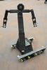
Alasdair Ryan Posted January 5, 2012 Posted January 5, 2012 (edited) Here is a idea i think you could power it from ether the outside or inside: Edited January 5, 2012 by Alasdair Ryan Quote
Burf2000 Posted January 5, 2012 Author Posted January 5, 2012 Here is a idea i think you could it from ether the outside or inside: But how would you fit that to the actual wheel Quote
Alasdair Ryan Posted January 5, 2012 Posted January 5, 2012 Em.......... i have not got that far yet. Quote
allanp Posted January 6, 2012 Posted January 6, 2012 You would mount the wheel onto an undriven turntable, then drive the droid wheel. technic pins/axles will fit in the outer ridges of the wheel. Quote
Recommended Posts
Join the conversation
You can post now and register later. If you have an account, sign in now to post with your account.