gheneli Posted December 1, 2025 Posted December 1, 2025 (edited) This MOC was designed mainly as a display model. I started with the intention of designing a livery for it and creating stickers, but that turned out to be quite a handful. If anyone here is more experienced with stickers and is willing to collaborate on a livery design for this car, let me know. This design started back in 2023, it was one of my early projects when I decided I'm gonna focus on learning how to design Lego Technic. I knew this once I realized I've always been more excited to design my own things rather than building sets or other people's MOCs. Unfortunately, back then I could only work on my Lego projects in my spare time, as I had to work full time, but in the last 6 months, I've been able to take a break from other projects and fully focus on finishing a Lego design. So this Camaro happened to be the first of many. I'm also a big fan of compact builds, utilizing as much of the available model space as cleverly as possible (a good example of that is the 42209 Volvo L120 Electric Wheel Loader), as I love displaying them around my apartment and I find 1:8 scale cars ridiculously big, so you'll probably see a lot of medium sized designs from me in the future. Still, that doesn't mean I will never release a 1:8 car. But today is all about this NASCAR Camaro ZL1, so I will do my best to present every single feature here. Enjoy! PROPORTIONS The most challenging part on the profile of the car was, of course, matching the side window and roof angle. The roof starts in the front a bit more curved upwards (and taller) than the street car version, so the curved panels work very well here and also help connect the sun strip flawlessly, without any gap. To match the proportion and height of the side window, I had to lower the top of it by half a stud, since leaving the window line at the same level as the roof didn't feel quite right. Below you can see how the panels connect to form the front of the roof. The sun strip had to be connected with gray pins because the middle panel piece (where the antenna sits) has that hole which conflicts a bit with the angle of the sun strip, but the gray pins allow enough wiggle to negate that problem. The roof flaps were an important feature and another challenging thing was to design the negative space after positioning the flaps (basically designing the hole shapes they insert into when they're closed) For the left side flap, things are pretty straight forward, since it's positioned horizontally, but the right side one sits at a 45 degree angle, so I had to use the new 3x3 triangle panel to create that gap angle. The hole you see on the new triangle panel also helps because it is used to insert the knob for the HOG steering. So yes, I was pretty happy with that one. ENGINE The engine (fake) is a regular V8 with working pistons, nothing fancy about it. And yes, I managed to fit the usual Lego engine blocks, even thought a V8 feels too big for the 1:12 scale if we compare it to the size of the real engine, so it reaches a bit too far into the cabin. A V6 would've been the perfect size. But I thought since there's enough room, why not? The hood is propped with a rod that automatically locks in place after you open the hood. Yes, it's not exactly the same as the real car, unfortunately, as I didn't have enough room (even if I'd opted for the smaller engine) to recreate the hinged props used on the real car, because they need a lot of room to close. You can also see the airbox sitting above the engine and the safety tethers made using the string with end studs. The hood design was completed using the new mudguard panel from the 2025 Bronco set, which is only available in red, for now. This new panel helps perfectly complete the curvature of the gray panel assembly in the middle, while also allowing enough room for the blue gear, used for connecting the steering rack to the HOG knob on the roof. The front grille and headlights assembly was especially hard to design. I used curved slopes to recreate the curved headlight areas while also managing to place them in between the lines of angled panels. The whole assembly is also slightly tilted forward, recreating the headlight angle of the real car from the side view. Since I had to use a hinge in the middle, to connect the slopes, there was no way of adding the Chevrolet logo, unfortunately. But, you can add stickers to recreate the real headlights and grille prints. Pretty accurate, since the real car has prints as well (fake headlights). TRUNK The trunk can also be opened to reveal the red fuel cell. A rod can be used to prop it open, this time an accurate design, as I've seen this used in many stock car trunks. Of course, there's also the fuel inlet that uses the two-hose system that leads to the fuel cell. One hose for the fuel, the other for venting the air from the fuel cell, thus allowing for a fast refueling. Pretty smart. I love how human ingenuity helps create better and better designs. Once the fuel reaches the cell, it goes out through the fuel line, designed here using a Lego flexible whip, going through a fuel filter (also red) and then moving on through the cabin all the way to the engine bay. On the left side of the trunk, you can see the (vapor) breather tank, connected to the oil tank through a breather line. You can also notice the fire hose nozzle (in dark red color), part of the automatic fire suppression system. And of course, the safety tethers, same as with the hood. SUSPENSIONS Front: double wishbone Rear: realistic truck arms with Panhard rod Again, I'm pretty happy with the design of the truck arms, even though again, the whole thing is based on the wiggle room of a gray pin, so there's very little range of motion. But, the good news is we don't need much suspension travel here, since the ride height of this car is very low, so, it works. I also love how I managed to align the gray sloped panels underneath with the angle of the truck arms themselves (see below). Besides the differential, you can also spot the oil tank and also the gear cooler on the opposite side of it. And of course, you can also see the exhaust pipes going from the engine to the right side skirt. FULL ROLL CAGE It was quite important for me to capture the real full roll cage as accurately as possible and incorporate as many bars as I could. I particularly like the long 16 link bars connecting the roof to the trunk. Even thought they're not that sturdy, they kinda contribute to the structure of the frame. Of course, using liftarms instead of those links would've made the structure crazy strong, but it was too much of a compromise in terms of visuals, as the liftarms looked too bulky. The side protection plates of the real car are also a bit curved on the ends, I tried using some panels in the early prototype stages, but the structure was lacking, so I had to use those gray frames instead. Below you can see an early version of the roll cage design. Notice the side anti-intrusion plates were more accurate to the real thing, but I needed a more solid frame. NACA DUCTS & DRIVER COOLING SYSTEMS Two NACA ducts are used for rear brake cooling (one on each side) and another one (on the right hand side) used for the gear cooler underneath. For the driver, two more NACA ducts are used on the right side of the cabin to help with cooling. You can also find one of the ducts going behind the driver seat, where the air is being cooled and filtered, then taken through a hose that connects to the driver's helmet. Below, in this view through the rear windshield, you can notice the breather line on the left and the brake cooling hoses, but also the wedge adjustment tubes running from the roof to the rear suspension. In real life, you can adjust the tension on each of the rear suspensions to balance the car and improve handling. Unfortunately, the 1:12 scale is way too small to include a functional mechanism of such. Below you can also notice the ECU (Engine Control Unit) on the dashboard. Below you can see the two fire bottles positioned inside the cabin, one is manual and can be used by the driver, the other one is automatic and uses two fire nozzles, one for the engine bay, one for the trunk. You've already seen the trunk nozzle a bit earlier. BUCKET SEAT I consider this seat design to be a happy accident, since I never would have thought of such a way to connect those side panels to the main seat assembly, but one day it simply clicked into place. I was mind blown. I'm not gonna spoil how the panels are connected, but I guarantee you'll love it. Below you can see an earlier version of the bucket seat. I also noticed some of the real head surround designs are asymmetrical, the left side being shorter, and I believe it's so that the driver can have an easier time climbing into the car. And here's the whole assembly including the leg protection and the pad in between the driver's knees (yes, another 3x3 triangle panel), to hold his/her legs in place in case of a rough collision. There's also a simulated H-pattern gear shifter, using a rubber connector to hold the stick. FINAL DETAILS To end this presentation, I'll leave a few more renders and photos of the car. Some are from quite early development, some are from late stages, and the photos are of the final design. If you've read the whole thing, I hope you enjoyed all the details I've managed to incorporate into this design and thank you for taking the time to check my MOC. Don't forget that you can find this design on Rebrickable (PDF instructions). Edited December 1, 2025 by gheneli Quote
N1K0L4 Posted December 1, 2025 Posted December 1, 2025 Man this is awesome! It's amazing how you made it so accurate, even on mechanical level. Just when I thought you were done with mechanical details you just have another paragraph :) I'm most surprised about the roll cage and how accurate you made it, you did a great job with this model. Quote
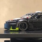
Lipko Posted December 1, 2025 Posted December 1, 2025 This is super awesome, but somehow the photos are not on the level the model would deserve. Even the renders are messy... The shaping is mindblowing but it's hard to appreciate it because of the photo quality. Quote
jorgeopesi Posted December 1, 2025 Posted December 1, 2025 Awesome car with a great detailed construction congratulations. Quote
VPtechnic Posted December 2, 2025 Posted December 2, 2025 Great work, what an exceptionally detailed model. As someone who doesn't know much about NASCAR, it was really fun and interesting to read the descriptions. Quote
2GodBDGlory Posted December 2, 2025 Posted December 2, 2025 Nicely detailed! Thanks for doing a detailed writeup, as well. I also appreciate the effort put into the rear suspension! I do hope you manage to get some stickers done at some point Quote
Jundis Posted December 2, 2025 Posted December 2, 2025 This thing looks really mean and with realistic proportions. Especially the whole chassis structure is so detailed. Fantastic work! Quote
Aleh Posted December 2, 2025 Posted December 2, 2025 I think this is one of the best MOC presentaions on this forum last years! Very well done! Quote
gheneli Posted December 2, 2025 Author Posted December 2, 2025 (edited) 17 hours ago, N1K0L4 said: Man this is awesome! It's amazing how you made it so accurate, even on mechanical level. Just when I thought you were done with mechanical details you just have another paragraph :) I'm most surprised about the roll cage and how accurate you made it, you did a great job with this model. Thank you! Yes, I was amazed myself to see how many details I was able to incorporate. The downside is that the part count stacks up and the costs of building it increase. 17 hours ago, Lipko said: This is super awesome, but somehow the photos are not on the level the model would deserve. Even the renders are messy... The shaping is mindblowing but it's hard to appreciate it because of the photo quality. I can't really argue with that. I also noticed some weird angle deformations in my photos and it's probably because of the camera lens. I don't have any professional equipment and it's probably the first time I had to photograph a product for a presentation. As for the renders, I'm using Bricklink Studio, which is not exactly rich in options when it comes to lighting and such. Without heavy editing, you can't really get anything nice in Studio. I wanted to try Mecabricks but when I imported my model from Studio, I had a ton of missing parts and it seemed too much of a struggle. 13 hours ago, jorgeopesi said: Awesome car with a great detailed construction congratulations. Thank you! 9 hours ago, VPtechnic said: Great work, what an exceptionally detailed model. As someone who doesn't know much about NASCAR, it was really fun and interesting to read the descriptions. Thank you! I was eager to share all the info I've learned throughout my countless hours of research. I'm really happy you found it interesting! 8 hours ago, 2GodBDGlory said: Nicely detailed! Thanks for doing a detailed writeup, as well. I also appreciate the effort put into the rear suspension! I do hope you manage to get some stickers done at some point Thank you! Yes, hopefully I can get more color options for the panels as well (a green Porsche is coming next year, maybe that will add more color options) and hopefully manage to get some stickers designed. I've seen many people have so much trouble with matching the part colors, so, at least for the moment, the stickers part gives me anxiety. 5 hours ago, Jundis said: This thing looks really mean and with realistic proportions. Especially the whole chassis structure is so detailed. Fantastic work! Thanks! 1 hour ago, Aleh said: I think this is one of the best MOC presentaions on this forum last years! Very well done! Thanks! I appreciate it! Edited December 2, 2025 by gheneli typo Quote
N1K0L4 Posted December 2, 2025 Posted December 2, 2025 38 minutes ago, gheneli said: The downside is that the part count stacks up and the costs of building it increase. Definitely worth it :) Quote
Recommended Posts
Join the conversation
You can post now and register later. If you have an account, sign in now to post with your account.