
nico71
-
Posts
462 -
Joined
-
Last visited
12 Followers


About nico71

- Birthday 12/07/1988
Recent Profile Visitors


-
 Thanks David for the updated edition ! I have not read yet but this is still a reference book for who are interested of want to create clock. Bravo for the works !
 -
Nico71's Creations
nico71 replied to nico71's topic in LEGO Technic, Mindstorms, Model Team and Scale Modeling
When you need a compact fake engine, without metapieces like 2×2 cylinder or new cam and piston , this is not easy to create. You have to make a functional model, without being blocky and if possible nice to see, top of the cake if it is easily removable and not part of the structure. During my works on different cars and trucks, I have designed several compact fake engines in different configuration and building style. Today I propose them for free in a collection of instructions and 3D model. Feel free to build it, look how it is made and reuse it. Each engine has its particularity : Nissan 4 Inline (based on LZ20BT, used in my Nissan Skyline KDR30) : longitudinal, rear wheel driven, 2l axle piston, beam to hold them, brick-built crankshaft, easily extendable to 6 inline Cummins 6 inline (based on X15, used in my Western Star 6900 Twinsteer) : longitudinal, 2l axle piston, stacked 3l connector to hold them, liftarm-built crankshaft, easily extendable Citroen FWD 4 Inline, (based on 11D, used in my Citroen Traction), longitudinal, front driven (gearing on the front), 2l axle piston, stacked 2l connector to hold them (when the 3l connector is too expensive), brick built crankshaft, with half stud connector for the chassis mounted if you want to place as low as possible with a 12t/12t spur gearing CAT V8 (based on CAT3208, used in my 6×6 Offraod Truck and Kodiak), longitudinal, 2l axle piston, angled stacked 3l connector to hold them, liftarm-built crankshaft, easily extendable Honda 4 transverse inline (based on B16, used in my Honda CR-X Del Sol), transverse mounting, gear inside the liftarm-built crankshaft for front wheel driven car, 1/2 pin piston on 1/2 beam, extendable to 5 cyl, no more Instructions and 3D models : https://rebrickable.com/mocs/MOC-238705/Nico71/free-engine-collection/#details 😀 -
Nico71's Creations
nico71 replied to nico71's topic in LEGO Technic, Mindstorms, Model Team and Scale Modeling
New instructions for a 14-year old model, the Integraph ! If you are allergic to maths, run ! A LEGO Technic replica of an Integraph, a mathematics instrument created in 19th century by Abdank-Abakanowicz, for plotting the integral of a graphically defined function. Original model (Coradi edition) : How it works : The grey chassis with wheels move in x axis, the input stylus along the y axis. The stylus is placed on a sliding sub chassis with a slot. On this slot come the carrier which is connected to the main orientation arm, so when the stylus move, the orientation of this main arm change. On this main arm, there is a sliding mechanism which hold the red carrier. This red carrier is build in a parallelogram way, in order the orientation of the two beams remains parallel. And on the extremity of this red device, the rotating beam is connected the contact wheel. So when the stylus input moves, the main arm rotates, and the orientation of this main arm is transferred to the contact wheel. The contact wheel is mounted on a carrier which can freely slide left right in y axis, and hold also the pencil with rubber band, plotting the output graph. The trick is that the contact wheel acts as a tangent wheel where its orientation will defined where it goes by acting on the carrier, being free of moving on the chassis. When the tangent wheel is aligned with y axis, the carrier does not move. When it is angled, the tangent wheel forces to displace laterally the carrier, and as its orientation depends of the y value, it moved along the differential curve and plotting the output graph. But why its integrate ? Because by definition, the inclination of the tangent of the integral curve -the slope or gradient- is equal to the ordinate of the initial curve to integrate (differential curve). If you look the machine in the reverse order, and follow a curve using the tangent wheel, the orientation of the tangent wheel define the gradient of the curve and so its derivative on each point which is the Y value. All the mechanical complication around are just to transform translation into rotation movement, and decouple each movement to be independent and not dependent of their position with the different slide and carrier. The applications of the integraph was numerous, calculate or divide areas, determine centres of gravity, calculate moments of inertia or stability, load and resistance, and solve algebrical equations like simple differential equation. Compared to a planimeter which gives the area result under the curve, the integraph give the representation of the function (primitive) so further calculus can be done. Therefore it was use in applied mathematics and physics, civil engineering with earth transport and bridge design, electricity with electromagnetism, shipbuilding, irons constructions, optics and ballistics with displacement and velocity determination for instance. Example of result ( f(x)=x and x²+y²=r²) These types of machines reached their peak with the mechanical differential analyser and balistic calculator in the twentieth century and then decreased in popularity with the advent of the computer. Video : Some additional resource : Animated Diagram Online and Displacement simulation (youtube) Wikipedia Page Mathsinstruments page about an integraph Bruno Abdank-Abakanowicz books from 1886 (author, chap 3. french) Integraph Page on Drawing Machine Instructions : https://www.nico71.fr/product/integraph/ Bill of material : https://rebrickable.com/mocs/MOC-237895/Nico71/maths-instrument-integraph/#parts For the model, I used a quite rare boat weight ref 73090. You can replace by any heavy part of about 50gr or use the alternate LEGO weight setup below (remove boat weight, add the displayed partlist, use the weightreplacement pdf). How to use it : Fix the paper, ideally A3 for both input and output, on the support with tape Place the integraph parallel to x axis, and the stylus on the smaller value in y. Place the tangent wheel carrier on the middle of its travel. Displace the integraph along the x value (horizontal left to right) while following the curve with the stylus (vertical y value) You can help the yellow sub chassis to move, as wheel as the tangent wheel carrier if it get stuck It is easier to be two to operate the machine (on for the x axis by holding the wheeled chassis traight, one for the y axis to follow the curve with the stylus) Ensure the surface is plane and the pencil touch it without too much force (do not lift the tangent wheel) If a part of the curve is missing, you can draw by hand if you have integrated a continuous functions -
It is made in Chinese bricks but yes it is quite nice to build its own creation :)
-
Hello ! I have published the design secrets video about this creation. If you like deep dive into technique, have a look ! (english spoken, 13min) : Regarding the first use ofsplit connector + heavy cv join, ApachaiApachai told me he was inspired by xfeelgoodx, so I credit here for that brilliant idea : https://rebrickable.com/mocs/MOC-77951/xfeelgoodx/monster-jeep/#details
-
Nico71's Creations
nico71 replied to nico71's topic in LEGO Technic, Mindstorms, Model Team and Scale Modeling
Thanks for the post and picture. But your axle is nowhere a 11l knuckle to knuckle axle, but a 13stud. This is why you have room to place the servo like that and you can use 5l suspensions arm without problem. Attention, the use you do of the suspension knuckle 6571 on the geared hub is problematic as this piece lack a bevel on a side, so it collides against the geared hub and make it force when steered. It is better to use the new 3l suspensions arm or the 5l in your case. Also, to me you can not use the daytona differential on your axle, but I can miss judge, let me know if this is correct as you stated it works. Have a look to the my axles on rebrickable, https://rebrickable.com/users/Nico71/mocs/ The constructions is different because of the constrain of 11l width, that is why I have waited to get the news 3l suspensions arm from the Bronco. If you want a similar axle as yours in 13l width, have a look to my Kodiak axle here : https://rebrickable.com/mocs/MOC-155168/Nico71/chevrolet-kodiak-c70-control-version/#details -
Nico71's Creations
nico71 replied to nico71's topic in LEGO Technic, Mindstorms, Model Team and Scale Modeling
Thanks ! If I fit the Daytona diff, it collides with the servo, so I think you raise by one stud the servo on your model, which is not possible here because on the top it should be room for the fake engine, so I have made to compromize. If you have link on your work, let me know. For the suspension arms, there are angled to have more ground clearance and better secure the cv join and axle inside the diff. It is not illegal to my understanding as it doesn't force on the part but use the natural play, but clearly "out" the grid system. Thanks ! -
Nico71's Creations
nico71 replied to nico71's topic in LEGO Technic, Mindstorms, Model Team and Scale Modeling
A small post to let you know I issued 3x free instructions for 11l motorized front axle using the news 3l suspensions arms from the Bronco. Background : The release of the new 3L suspensions arm is a very good news for axle building. The previous 5l arms was too big to create short width axle with gearead hub. So it was mainly use for 1/17 truck with 62.4mm wheel. After buying a LEGO Bronco, I start making 11-stud width axle which opens a wide range of LEGO Truck. Indeed, for trucks which have large tires compared to their width (for instance 13R22.5 14R24 or 16R20 like heavy hauler, logging truck, offraod truck, or military one), it is mandatory to reduce the width of the axle by 2 studs to comply with the scale if using the 62.4mm wheel. So here are the result, a 11-stud wide motorized front axle for truck with big tires at 1/19-1/21 scale, with free instructions and 3D models. Available in 3 Versions : No Onboard Servo : Onboard PF servo : Onboard PU (control+) Version : Specs : – 11-stud width (knuckle to knuckle), 13cm wide with 62.4mm wheel – Geared hub + CV-join (only two needed, other are standard CV-Join) – Inclined underneath suspensions arms (can be considered as illegal but give better ground clearance and differential secured) – Equipped with a 28t simple bevel differential, No onboard version compatible with all the differential. Onboard version NOT compatible with red 28t of yellow 22t crown – Steering with rack and pinion, 4 studs distance from the knuckle axis to use 180° of rotation of the Servo motor without forcing on axle end stops – Suspended with 3 or 4 links (2+1 central or 2+2 lateral) + 2 springs with lateral movement constricted (can be replaced by harder if needed), no need of Panhard rod but you can add one for better stability – Simple chassis for suspension mounting included (can be used for car depending of the scale, like pickup truck) Downloads : PDF instructions and 3D model (Ldraw+Studio) for building convenience https://rebrickable.com/mocs/MOC-236196/Nico71/11-stud-motorized-front-axle-no-onboard-servo/#details https://rebrickable.com/mocs/MOC-234780/Nico71/11-stud-motorized-front-axle-onboard-pfs-servo/#details https://rebrickable.com/mocs/MOC-236302/Nico71/11-stud-motorized-front-axle-onboard-pu-servo/#details Have a nice build with these, please credit me if you reuse the model in case of commercial use 👍 Also, for tracking, here is the dedicated topic to my 6x6 Offroad Truck released in May if you missed it : -
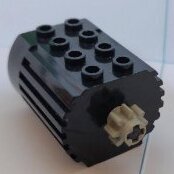
Thanks ! I wanted at first to get the two speed gearbox motorized but it takes too much space and so the baterry box was not at the lower position (in the bed instead) so I prefer to get the gearbox manual and have a flat chassis with the battery inside. I see it as a two-mode shifter (speed or torque) and add an interaction like the openable elements even if it is motorized, it is nice to interact physically with it. The gearbox is operated by red levers on each side, because the fake engine axle pass on the center. So I use 4l axle with stop to prevent the axle to be easily pull out when we remove the knob : Yes the steering 12 bevel gear which act as an articulated gearing (replace a cv-join) is placed inside a U shape (dark grey on the picture) which is articulated on the perpendicular axis of the bevel gear : For the round cylinder 2x2 on first rear axle, you are right ! It is for replacing the axle joiner and fill the gap to avoid the small tan 12t bevel gear to fall down, because the CV join axle is not sticking out (because I use a thing triangle to lock to drivetrain so it lack 1/2 stud). You can see that I do not need that on the last axle : For the wheel cover, I like to add more details now with non-technic pieces, but I trying that these part are not mandatory for structural. Like that, people can build a cheaper and simplified version if there had not all this small detailed piece (bar, clips etc), so the design will be simpler but still nice to see as composed of technic parts (the bed and flatbed require 114x 1/2 pins for the smooth finishing with tile for instance). Thanks ! It is a good base at this scale but it can not compete in heavy truck trial I think over bigger model with bigger wheel, as it lacks some ground clearance and breakover angle. But the drivetrain and suspensions setup can be reuse and extended to match the 81mm wheels without too much trouble, so you will have a very solid trial truck ! Thanks Jundis, Steph and Paul for your comments !
-
You are right, in fact I do not have these gears so I use the old one ! I am glad that you notice the oscillating bevel gear instead of CV-join on the steering, it makes me gain some space. Tiny truck but full of tricks ! Kudos to Legov94 for the original idea (credited in the text) ! It is indeed a very effective way at this scale to avoid having the walking beam too high, like on my Western Star 6900 TS.
-
Hello everyone, I create this topic to present you my new creation, a motorized 6x6 Offroad Truck. I usually post in this topic, but I think it will be better for forum search to now separate it as it start becoming very long. Let me know admin if this is a problem. The model : A 1:20 scale motorized offroad truck, equipped with 6x6 transmission, working fake engine, steering, full suspensions, manual gearbox, and openable elements. Completed with 80's look with colorful side stripes, quite efficient and compatible with different power sources (Infrared PFS, Buwizz, 2.4Ghz controller). Specs : Offroad model based on International, Western Star and Scammell Truck from 70-80’s Dimensions : 41.5 x 13 x 17cm, Scale : 1/20, Wheels : Ø56mm Power functions Motors (2x L+1x Servo Motor), battery source : PFS, Buwizz or 2.4GHz 6×6 drivetrain with no differential, primary reduction : 12/20 12/20 12/20 Two speed gearbox (manually operated), ratio : 16/16 or 20/12 Removable working CAT V8 fake engine Steering with rack and pinion, cv-join and oscillating bevel gearing Front suspension : live axle with 3 link arms, 2 spring and 1 Panhard rod Rear suspension : walking beam axle with parallel links and 2x Panhard rod Openable hood with two locking positions, openable doors Openable and removable sideboard bed, flatbed with end roller underneath Compatible with regular Power Functions Battery or Buwizz / 2.4GHz Battery See in action : About the model : I wanted to build for a while a successor of my Western Star 6900 with AWD this time for more offroady session. So I chose a 6×6 truck with the same 56mm tire and started in 2024 ,first with the chassis and drivetrain. I incorporated some good ideas from other people that I must credit : Gyenesvi for the floating U shape connector on the front axle, enabling to remove one CV Join and gain space. The use of the larger Split connector to fits the heavy CV join, from Apachaihapachai, enabling to build a compact and sturdy front axle. Finally the vertical mounting of the towball arm, from Legov94, to lower the oscillating point and improve the suspensions movements. All these solution enable to build in a more compact way, and so offer more space to place carefully the motors and the battery box for weight distribution, as well as having more function like the manually operated gearbox with a slow and fast speed. Layout of drivetrain, steering, and suspensions : I also use a bevel gearing for the steering axle as an oscillating axle, to avoid using a CV join and gain space to place the servo motor in the cab, and keep the hood empty to fit the V8 working fake engine. As usual, the engine is removable easily, as well as the sideboard bed, which are functions that I like for playability. In addition to that, I chose to make the truck in one color with colorful stripping, at first white, but then in black with red / orange / yellow stripe, which remember the Toyota or Kenworth color scheme of 80’s truck. It result in a nice, sturdy and efficient truck, while keeping the adaptability features for upgrade, like swapping primary gears and battery to fit what people have. Of course the performance are limited to the tires size and the lack of portal hub, so while the approach angle is good, the breakover one is not (as shown in the video). It remains a not-so-heavy truck with nice look which performs safely on rough terrain. 📕 You can find more picture and the instructions on my website : https://www.nico71.fr/product/6x6-offroad-truck/ (instructions are in two versions, PFS IR and Buwizz, with buwizz profile and tutorial) 🧩 Rebrickable inventory : https://rebrickable.com/mocs/MOC-219862/Nico71/66-offroad-truck/#parts Let me know what do you think, do not hesitate if you have questions 👍
-
Nico71's Creations
nico71 replied to nico71's topic in LEGO Technic, Mindstorms, Model Team and Scale Modeling
A new creation quite unusual, a 30ft workboat, based on Jemar Norpower 30ft boat, with dual winch with ratchet and probe, front winch, seismic element supports, and opening engine cover. Specs and History : Dimensions : 46x19x25cm (without end probe), scale 1/23, 1789 pcs Dual winchs with 2/4mm hose with ratchet mechanisms on each Front winch with ratchet (no anchor) Two seismic probes Retractable side sensor (sliding mechanism with two sections) Articulated rear gantry for support the probe hoses Articulated side arms for probe hoses recovery Openable rear guardrail Openable engine cover Articulated rudder (non functional) Detailed offset cabin with interior Support Frame Original Model : This boat is used for seismic exploration using acoustic probe in the sea. The 1 km cable is unloaded with the winch and pull in the sea, where the end probe can move to adjust its direction and depth and communicates with the boat directly though the cable. After the data acquisition, the boat use the telescopic cable lifter and the two flaps to lift the cable from the sea to wind back and get the probe. The cable lifter can also be equipped with fixed acoustic sensor (displayed on the LEGO model). You can see the real boat in action here In action : About the model : This model was designed in 2022, based on Jenmar Norpower boat with Sercel Livery. The aim was to display in a showroom to show the functioning of the boat. That is why it doesn’t float and is not motorized. It was nevertheless quite a challenge to reproduce the boat, especially the hull and the colored decks with all the details, as well as the seismic specific functions to be functional without affecting the sturdiness of the model. After some demands and good feedback on the overall design, I decided to make the PDF instructions as it can be easily modified to accommodate other purpose such as fishing, rescue, research etc. The instructions is available on my website and rebrickable. -
Nico71's Creations
nico71 replied to nico71's topic in LEGO Technic, Mindstorms, Model Team and Scale Modeling
Thanks ! Thanks ! Indeed the sidepod was really difficult to do, that is why the scale matter. Bigger, it would have not be that clean I think, here the different size of lego elements matchs well the shape. -
Nico71's Creations
nico71 replied to nico71's topic in LEGO Technic, Mindstorms, Model Team and Scale Modeling
Thanks ! Indeed, there is not so much reaction since the social media advent, but some people are still on forum or use rss feed so I post here. -
Nico71's Creations
nico71 replied to nico71's topic in LEGO Technic, Mindstorms, Model Team and Scale Modeling
Thanks for letting me know !