
Joostv
-
Posts
17 -
Joined
-
Last visited
Content Type
Profiles
Forums
Gallery
Everything posted by Joostv
-
 @Timewhatistime I have added a low-res / minimum size version that is under 5MB at the cost of visible compression in the instructions. Please, let me know if this works.
 -
Thanks! A quicker / easier way to wind up, like pulling a thread as you suggested, would be great. The problem with adding it to the dino itself would be that it adds weight and impacts the balance. Adding a spool to the wind up tool should be feasible, but it would require an additional solution to wind up that spool. Which could be something simple, like rolling it over the floor. That would be worth a try I think. Another solution would be something electric, like a Lego version of @2GodBDGlory's drill solution. Hi @Timewhatistime, I didn't know about this size restriction. I will try and see if some compression can be achieved at the cost of resolution and will upload it as a seperate version. This way you should be able to select the smaller version. Thanks! and thanks for sharing that solution! I will be exhibiting (for the first time) next month and will definitely bring along my cordless drill 😉
-
Thanks, glad you enjoy it 😊 Thanks! Have fun 😊 check the first pages of the instructions for alternative parts of you don't have DIGatron. Thanks 😊 I watched road runner a lot as a kid 😊
-
Thank you both! 😊
-
Thanks for the positive feedback all 😊
-
Thanks 😊 😂 Thanks! Thanks! I learned to announce tests of this one. First succesfull test run in the living room caused a little scream.. Bit too life-like 😉 Thanks 😊
-
Thanks 😊 Thanks 😊 I was pleasantly surprised by the performance of the pull-back motor in this application.
-
This is a little experiment with a pull-back motor. The idea was to do something other than wheels, so I tried legs 😊. I got this to work quite reasonably as you can see in the video. The idea was to have a linkage for the feet that is linear on the front to back movement, but moves in an arc on the back to front movement so the feet can overlap. The overlap is in the center. I have made instructions (free ofcourse) which are here: https://rebrickable.com/mocs/MOC-252160/MejoliDesign/md007-running-dino-experiment You can just scroll through the PDF and see the dino from various angles. This will give you a better idea of how it was built. I managed to include a moving tail, which really helps balancing the dino. With the tail the run was much more stable than without it. I have made attempts to make it a bit prettier, but basically any additions downgrade performance or upset the balance. The sprint is short: 1 tot 1.5 meters. If the power runs out it falls, and power runs out quickly with a pull-back motor. Depending on how well it was positioned at the start and how well you guide the first step the sprint will go straight, curved or it will do something weird like hop on one foot and rolling on its back. I think you can compare it to rolling a coin: it takes a bit of practice. In one way the pull-back motor is the excellent choice for this. The advantage of the pull-back motor is that it will accelarate hard if load is removed. This is precisely what happens in moments when both feet are off the ground. Due to the acceleration of the pull-back motor in this moment, the feet will quickly regain contact with the ground again. You can see these little accelerations in the slow motion part of the video if you look closely. I had quite a lot of fun experimenting with this. So if you want to have a bit of fun building something small that jumps/runs/hops/flaps/... I recommend playing around with a pull-back motor 😉
-
Thanks 😊
-
Thanks! To be honest, if it fails on Lego Ideas I'll likely create a smaller 'inspired' design with a different function (not playing Tic-tac-toe) and share instructions of that. This design has some really hard to source parts, which is something I would change when sharing instructions. Different route, different (self imposed) limitations 😉
-
@Johnny1360 Thank you and have fun 😊
-
@Nalyd997, @Morgoth924, @Kai NRG, @Davidz90, @MKJoshA Thank you 😊 Thanks 😊 And we seem have two hobbies in common then 😉. I was also close to dismissing it when I googled the possible number of game states for Tic-tac-toe (Google came up with an insanely high number). Ofcourse most of those states are ludicrous and moves that no one would ever make. Correct, when the memory is read by the bars which push the and gates into vertical alignment in case the memory is 'high'/true. I think I may need to clarify the two 8-input OR gates: These large horizontal H shapes are the central connections between the input AND gates and the output AND gates. Basically all these AND gates "patch in" to one of the OR gates that connect all keys and fields. Crucially the arms that can block the memory also patch in to these OR gates. Thus the memory bits define which keys trigger which large or gate and what countermove will occur and also where the memory needs to go next. When I built the prototype it turned out that it was very testable during every step of the build. The advantage of that is that a building mistake can be fixed in time. Basically unit testing before integration 😉. The main risk for erroneous operation die to a building mistake is an error in the memory. This is why the memory can be reasonably easily removed. There are indeed a lot more possibilities, but I ran into the LEGO Ideas part limit. That is also why there is no win-lose indication. The signal is available, but the parts are not. If you press two valid keys without turning the dial, then currently there's no guard in place. A guard could be integrated and triggered by an additional OR in the middle in both the two large OR gates. Then be reset by a dial turn. That would require additional parts. A major obstacle to automatically moving the memory on a key stroke press, is that the memory readers must be lifted and this requires a user action. Turning the dial lifts the memory readers. This needs the power of the dial rotation and is supported by two springs (shock breakers) to push the memory readers up for memory reading, but also force them down to correctly read the bits. Central reset of the display was the original idea, but my solution didn't fit. The idea was a slider mechanism, gears had too much play and reset needs precision on all 6 axles. It's a bit finicky. The seperate controls never fail to reset each line. The different rotating directions for display reset is a last minute fix to an error I made. That is easy to fix and I can't image LEGO wouldn't do it if this became a set. A rubber band on the lever is definitely a good idea 👍 even as it is now. And to the last comment: Thanks 😊 and thanks for sharing the suggestions and taking the time to write it all down.
-
@2GodBDGlory, @mdemerchant, @Jeroen Ottens, @Siroco, Thanks for your kind words! 😊 Love those. I have seen a video of one with electric motor going crazy on a divsion by zero once. And thanks 😉 @Elysiumfountain, Thanks and congrats on passing 5K 😊, that house is a beauty! @Toastie Thank you very much! I can't quite describe it, but I'm genuinely touched. Thank you, this made my day 😊
-
Thanks 😊. To be honest about that frame, that solution was born out of necessity: I don't generally use white bricks, and most of my remaining bricks were all different kinds of white (some near yellow 🫣). So I went to a local store and bought a photo frame to cover that up. That looked a lot better. 😉 Thanks! Finding a way to integrate the reset knobs for the display was the main headache. The original plan was to mount them out of sight, but that didn't work out. I was glad I found a way to hide them as decorations. Thanks, and thanks for suggesting it 😊. Pretty much, yes. You can get errors if the machine isn't level (the old secretary with food out desk that is my little building corner definitely isn't level). And strong vibrations (like slamming the table it stands on) can trigger a display (shield/swords) to appear, but that's it. Thanks! And the last quote is actually true for WOPPR and this machine (the best possible outcome for the player is a draw) 😉 @1980SomethingSpaceGuy, @vascolp just wanted to say thank to you as well 😊
-
@JunkstyleGio, @blondasek, @N1K0L4, @pleegwat & @allanp Thanks 😊 I'll also answer your questions here: Q: question about lock-ups A: None on the interior, but the tiles that hide the technic holes on the liftarm on the sides (see image) have caught the housing of the dial once. It gave me quite a scare because I thought I had to dissassemble the whole thing. Luckily all I needed to do was press on the tiles and the problem was solved. I haven't looked into preventing this from happening again yet. Q: Question about inspiration A: Every once in a while I have some idea followed by the thought: "Would this be possible with LEGO?". Then I check if somebody did something like that before, and if the answer is 'no', then I get the urge to try and build it. I did magnetically dancing shoes once for pretty much the same reason. In this case there are some very cool builds around that do things with mechanical logic gates or mechanical computing, and some awesome electronic tic-tac-toe playing machines, but not something quite like what I had in mind. Q: Question about 18th century style and if something existed like this. A: The 18th century had lots of automata, these combined mechanisms with a styled exterior and often some animal that was animated by the mechanism. One of the most famous automata was 'the turk', which was a chess playing robot. It was a hoax: A human was hidden inside, but it has all kinds of doors to show the fake internal mechanism. Thanks again 😊
-
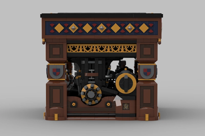
3 years ago I set myself a challenge to build a mechanical computer that can play Tic-Tac-Toe. I hope you like the result 😊. Final design: Open studless exterior in 18th-century style and medieval game theme, with Technic interior visible. Gameplay & limitations The machine starts in the center with 'X', which is represented by crossed swords. The player can play the bottom-right two fields. To play the other fields, the player can rotate the machine, so this isn't really a limitation. After that, all player moves are supported. The machine will reject moves on fields that are already taken (invalid moves). The machine can reach 25 different game states and 19 different game endings. The machine responds immediately to a player move, resulting in the player move (shield) and the countermove (swords) becoming visible almost simultaneously. After each turn, a single full turn of the dial on the side moves the memory to the correct next position. How it works I built a cross-section model to explain the mechanism. It is demonstrated in the video below. Summary of the video: The machine uses two types of logic gates: AND gates and OR gates. Signal direction is upward. Gravity is used to return the gates to their default positions, which significantly reduces the complexity of the logic gate designs. The logic gate network for a single response consists of: A first AND gate that reads one bit from memory and has the player key as the second input. The result is fed to an 8-input OR gate that is almost as wide as the machine And the result is fed to a 2-input OR gate that triggers the shield corresponding to the key An 8-input OR gate (almost as wide as the machine) The result is connected to one AND gate per field for triggering swords. And the result is fed to an AND gate handling memory addressing. A second AND gate for triggering swords, which takes input from the wide 8-input OR gate and a bit from memory. The result is fed to a 2-input OR gate that triggers the swords for the field. A shared AND gate for memory addressing, which takes input from the wide 8-input OR gate and a bit from memory. This drops an arm on the memory plate to block it at the correct position. In an end-of-game situation the arm is not dropped. The memory will move to end-of-game position as a result. The two OR-gates to trigger shield or swords, as mentioned earlier. The machine combines two slightly different versions of the above network so it can have two different responses at any time. The OR gates that trigger shields and swords are not duplicated, but triggered by both networks. The memory addressing for the two networks is different: One can skip multiple program steps. One always stops at the next step. As both networks are equally capable, each game state uses the network with the correct addressing behavior. All the logic gates are optimized to be as small as possible and to function next to each other without a seperating wall. The entire logic gate network is powered by a key press with a height difference of just one stud. For that reason, everything is mounted on rollers to reduce friction, and horizontal signal distance is limited as much as possible. The memory plate. Not in the video: Powering the memory movement The memory is pushed forward by a scissor mechanism. The memory does not travel the same distance for every player move, and I really wanted to have only one turn of the dial after every move. Therefore, the memory had to be powered independently from the player's action. I tried a lot of different solutions: The first idea was to let the memory fall down (move vertically). That didn't work because the memory was too heavy, and skipping multiple program steps caused excessive stress and force. The second prototype used a memory drum. This did not work well for reading the memory and suffered from bending stress on the central axle. The third idea used gears to transfer power from a weight to the horizontal plate. It had too much friction, sometimes causing the mechanism to refuse to move. It also made resetting heavy to operate. The last (and only succesful) idea was this scissor mechanism, still transferring power from a weight (the part with 'Lude Bene' on it) to the memory plate, but with very little friction. Powering the shields and swords The force of the user's key press is mostly dissipated after passing through the logic gate network and is only suitable for light triggering. Each shield and set of swords is powered by its own small weight. The weight is held in place by a mechanism that requires only a light trigger to release it. This works very well. I haven't got around to demonstrating this mechanism in images/video yet. Reset mechanism The video below shows the reset system (rewind the video to see another game demo first): Summary of the video: The display is reset using hidden knobs in the decorations on the sides. Turning these pushes the shields and swords backs and locks the weights that power them behind their triggers The memory is reset in three steps: The dial is turned half a turn. This lifts the memory readers, allowing the memory to move The handle is pulled, pushing the memory plate back. The dial turn is completed to read the memory and allow a new game to start. The central field remains unchanged. This is the first move of the machine (crossed swords in the center) Exterior The design is intended to look like an 18th century machine with a medieval game theme. The style is studless and I have avoided tile grooves where possible. I used panels (mounted backwards) instead tiles. The back of a 4 wide panel does show a small injection-mold mark, but this is less distracting than a tile groove. I also used a lot of half-plate offsets throughout the buildto hide tile grooves. This was mostly achieved by combining brackets with modified bricks (with studs on the side). Build experience, more images and future of the project If you have watched any of the video's to the end, it probably didn't escape you that I submitted this project to LEGO Ideas 😉. Like many others, I still dream of seeing my design on store shelves one day. Besides a rather prominent yellow button, you'll find additional rendered images and a description of the build experience there. In the creator update (which, for some reason, requires login), I included a technical description supported by animated gifs extracted from the first video in this topic. https://beta.ideas.lego.com/product-ideas/96a609c5-bffe-4df9-86a5-dbd005514159 Thanks for reading all the way to the end, Joost / MejoliDesign