
Guy_Walker
-
Posts
31 -
Joined
-
Last visited
Content Type
Profiles
Forums
Gallery
Everything posted by Guy_Walker
-
Hi Bajajoaquin Great build!! You've created an alternative mechanism for linking 2 lazy points which is more compact than the "one above the other" arrangement. There's no need for a long loop of track between the 2 switches and the mechanical linkage underneath is very neat. It's main disadvantage though is that you can't connect track to the central joining section, so cannot add more complexity. As you've found out, the simple 'double-lazy switch dogbone' layout is a bit limited. With 2 unlinked switches, you have a surprisingly long run, see auto_run page. I give this an ARL (auto run length) of 8/4 as I count the central 'missing' track between the 2 points. But linking the 2 switches produces a simple cross over, which halves the ARL to 4/2. A case of more complexity doesn't make a more interesting circuit. This is often what happens even with very large circuits. They easily reduce. Rotating the 'unlinked' layout by 90 degrees creates 2 separate loops which as you say is not APV. With the 'linked' layout, the 2 linked points act as a cross over, so rotating makes no difference. But still, nice build, and as you say, just a matter of finding some real use for it :-)
-
Yes - the wire links are simple but not very kid friendly Unfortunately, I don’t know of any links constructed using Duplo blocks I posted a Lego link solution a while back #144 PeterF has a long Lego brick link #180 and also a solution using Lego Technic pieces #172 But I guess Duplo blocks are just too chunky.
-
Just a quick photo of the auto-run layout described in my previous post #189. It is the first (upper) circuit, but with just 2 stages instead of 3. Each pair of points is linked with a wire loop as usual. It has an auto-run length of 12, which took the train 1 minute 23 secs. More stages can be added, with each additional stage more than doubling this time. Unfortunately the train times out (auto stops) after 2 minutes, although the electronics can apparently be modified (post # 170).
-
There’s quite a bit to it and multiple aims too. Good maths or good Duplo layouts :-) Yes you’re right, you can reduce the Xovers to 2, or even just 1, but the circuit ends up much bigger. I’ve not investigated using bridges, (a whole new dimension), but they do add interest to practical layouts. The other advantage of Xovers (besides compactness) is they help keep the track more rigidly fixed together. Especially the point pairs which makes the wire arch links more reliable. I'm not sure why Xovers are so expensive to buy though.
-
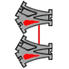
Yes -it’s easy to get carried away with the theory. It tends to lead to oversize layouts with far too many crossovers. But the method of joining small modular circuits together is useful in determining the behaviour of larger circuits. Here is a similar but much simpler example than my previous post. Using the single circuit on the left, connect loop to central track producing a series of 2:1 gear ratios. The overall auto run length is given by: 4 (2^c -1), where c is the number of circuits (pairs of linked lazy points). So 28 in this case. The layout also steps through all 8 combinations of its points as a cyclic Gray Code, which could be useful. The Duplo ‘auto switching layout’ built in post #182 had an auto run length of 10. Using 2 circuits as above will improve this to 12. I think that this construction method produces layouts of maximum length for any number of point pairs. No layout can have a longer auto run length for the number of points used. I don’t have a mathematical proof though. Btw, the above similar layout has the same auto run length of 28 but the train switches 14 points instead of 8. So a harder working train. (The layout can be built without the crossovers). I’ve updated the cr31 Auto Run page to reflect the above info.
-
First, an update of the auto switching layout in #177, with added ‘0’ and ‘1’ labels. Starting at a0 with all points set to ‘0’, the train traverses the following tracks between points: a0-c, c0-b1, b-a, a1-d1, d-b0, b-a, a0-c, c1-d0, d-b0, b-a The complete ’tour’ takes 10 stretches of track to return both pairs of points and the train to their starting positions. So this circuit has an auto run length of 10 tracks. Any circuit with 4 points always has 6 tracks, so some tracks are used more than once. Indeed 2 tracks are used twice and 1 track is used 3 times. All in the same direction, no track is bi-directional. Shown by chevrons in the diagram. Also btw, entries in bold show when points are switched by the train. You can see only the lower point in each pair (B & D) do the switching. So these ‘active’ points will in theory wear out faster than the upper ‘passive’ points A & C. A quick diagram of the connected circuits may help. The second (lower) layout is symmetrical, both circuits share a common track (b-a) and so remain in synch. This gives an auto run of 2 tours, a total of 2x10 = 20 tracks. Not a particularly long run for 8 points. The first (upper) layout is more interesting. You are connecting a track which is used 3 times (b-a) with a track which is used once (c1-d0). This creates a kind of 3:1 gear ratio. So starting at a0, by the time the left hand circuit returns to its starting position, the right hand circuit will have been visited 3 times. So producing an auto run length for the entire layout of 4 tours (40 tracks). Adding a third circuit to the right will increase the auto run length to 1+ (3x4) = 13 tours. Four circuits will take 40 tours etc. Each tour requires 10 tracks to complete. This is an efficient method to produce long auto switching layout sequences. However, it is not necessarily a maximum for the number of points used. The numerical series 0, 1, 4, 13, 40… can be generated by the formula t = (3^c -1) /2 where t is the number of tours and c is the number of circuits. Also note each tour takes 10 tracks and each circuit has 4 points. So for example, connecting 10 circuits together will require 29,524 tours to return all (40) points and the train to their initial starting positions. My train took 2 minutes (just after timing out) to complete one tour, so just over 41 days continuous running is required to reset the whole layout!
-
Wire arches work well if pairs of points can be held apart by a Xover. Layout #181 has 3 pairs of points but is unusual in using so few Xovers. Larger auto switching layouts tend to have many tracks crossing each other. I think its symmetry may make it less interesting to run though. Peter Nolan #183 -I’ll try out your ideas and report back.
-
Just a photo of the maximum run layout as described in previous posts #174 and #162. It is slightly more compact than the diagram in post #177. Both pairs of co-operative points use short overhead links - a 4mm diameter wire bent into a 5x5 inch goalpost shape. The train only just manages to complete the circuit (resetting all points) before it timed out, although I think I read somewhere on this forum that this can be disabled.
-
Cool! - long links rule! And it does save a lot of track, so they really are necessary. I’m glad you had fun with the layout. These ‘auto run’ circuits are quite good fun to watch. You feel like you’re getting your money’s worth or something. However, I’m not having much luck with the maths, so no idea what the best (longest) runs attainable are. I think this is a maximum for 2 co-operative points. This layout uses 3 co-op points. It might just be buildable but many of these larger circuits don't work out well with Duplo geometry. An equivalent interactive layout is on the cr31 auto run page. Good thinking - I did try using the ‘diverger’ piece as a random output generator. The train does not derail, but it tended to always choose the same side, so not than random unfortunately :-(
-
Wet afternoon so built the all important Flip-Flop (Distributor) circuit using a gang linked point. The lower ‘converger’ piece merges two tracks together. All the black pieces are smooth (for push-along trains) but the Lego loco didn’t lose traction. The circuit operated correctly with the train arriving at the converger upper and lower tracks alternately. This behaviour required an infinite circuit according to Adam and Greene, but they used only single (not linked) points (post #151 for PDF link). You’ll notice the lazy points are linked with a ‘low tech’ piece of curved coat hanger wire. This works surprisingly well for a quick set up. The slight springiness of the wire seems to help. Not sure about a long link though Peter. The problem with gang linking points under the track is the need to raise the track on bricks. This can lock the track together, which seems a good idea but without 'play' most layouts have alignment gaps and cannot be built. Maybe some kind of overhead link is the way to go? The solid construction of a large reliable train track computer is perhaps a very different exercise, requiring glue and screws to securely hold everything together for continuous operation. A major project for another time…
-
Hi Peter, If the long link is a problem, you could reduce it by adding an extra loop and some more track, like so:
-
That’s great! - a really neat solution I too was surprised at how low the forces are when the points are operated, especially when they’ve been ‘run in’ a bit. So I’m pleased you’ve worked out a non glue solution. I guess it’s easy enough to gang up more points too. I’ll try out something similar. It has to be very reliable though if a train track computer is to be left calculating away…
-
Peter, ahhh -now I see what you mean … but the answer is no. There is no other way of constructing two linked lazy points than actually linking two lazy points together. If there was I’d use it instead of having to glue point levers. Also, you’d be able to create a flip-flop point from just lazy and sprung points, which is impossible. btw here is a mock up of a possible Duplo flip-flop point: Even allowing for the sharp edges of the lever, it has problems: The point is one way only. Trains travelling from right to left are derailed 50% of the time It doesn’t work anyway. The lever cannot switch until all the wheels (loco front and back) have passed over it. This is why Duplo (or anyone else) doesn’t make train track flip-flop points. So I guess it’s back to the glue !!
-
Hi Peter, -reply to your post above... 1/ I’ve made the max run layout I mentioned last post interactive here. It is a "fun display layout" you might like. 2/ The inverted lazy point is interesting. It acts as a flip-flop point if the train returns back along the same track. So it can alternate between 2 sub-routines for instance. Might not necessarily be APV. 3/ I guess you could say the dual bypassed lazy point acts as a sprung point in some cases. However, it is really just a lazy point where the train is not allowed to 'correct’ the point. This is achieved by adding sprung points so the train by-passes the lazy point and doesn’t switch it. A useful component in some circuits. 4/ To create the equivalent circuit, replace each sprung point with its equivalent two lazy point circuit. So you will need 9 lazy points altogether (treat the central dual sprung point as two separate sprung points). It looks like this: I've shown the dual bypassed lazy point lower right in an equivalent position. Hope that helps :-)
-
Robert: Thanks, the interactive layouts do make a difference. This is why it’s taking some time because I need to re-jig the explanations and include other things. The javascript code is shockingly simple -we’ll have to compare notes sometime! I’ve had a quick look at LiveCode. I’m now looking at ‘maximum run’ layouts. This web page describes an 'Automated Switching Layout' built for shop window displays in the 1940’s. It’s really just a pair of linked co-operative points. I’m adapting the program I wrote to find similar knots to search for any other maximum runs. Not sure how to tabulate the results yet. As you live so close by it must be worth a visit to the ‘Grenoble guys’. It may provide some insight into a good project -computing with cars on a track maybe. Also very interested to hear their ideas on mechanical computing in general. But don’t rush, wait for some free time and enjoy it :-)
-
Hi Peter, Thanks for the neat diagrams, they help enormously. You’re right, they use less track and are more compact - so a better counter track layout !! A new right-most point will make the return loop bi-directional. Otherwise old or new. Yes, I avoided Lego and glue for quite a while for the same reason. But no alternative. It seems to work well. Maybe Duplo will add a stud or hole to allow normal connection to the lever under the point. Such a small cost I’m surprised there isn’t one.
-
Peter -great you discovered binary counting by mixing old and new Duplo points. Very interesting if your counter can use fewer tracks “by curling round in a kind of flower shape”. Do you have a layout diagram? Even just a rough scan… It takes the train longer to count higher because of the time taken to travel to and from increasingly distant points. You may be able to make the counter more ‘even’ by always returning the train via the furthest (most distant) point. As well as flags and balls you can make the point position more ‘visible’ by adding stickers with a ‘0’ and a ‘1’ onto the flat red part so each is revealed or hidden as the lever is moved. Correct traction is always tricky. Gear wheels tend to have smooth edges. I have been looking at anti-slip tape so I could use black crossover and short track pieces from the ‘push-along’ train sets. Rubber band ’tyres’ on the train wheels and stick on rubber strips might be enough…or might not. I’ll have a look into it.
-
Robert -the infinite points are required for each distributor -not for the (potentially infinite) track !! The Chalcraft and Greene report (in my previous post) assumes (page 8) that you have a string of network cells to represent each ‘0/1’ position on a tape. Their diagram shows just 3… Each network cell requires a distributor. These are not easy to construct from lazy and sprung points. As they say: ‘the reader is strongly advised to try constructing one of these - it makes an infuriating problem’ (page 10) Their solution is to use an infinite number of sprung points. One for each time the distributor is used. They did not allow themselves to use linked points. Not too sure exactly why … I think it adds a whole new dimension of complexity. Maybe someone can tell us!! However, it does reduce the number of points required for each distributor from infinite to 3. But you still need many network cells. The Lego Turing machine that you linked to for instance has 32 tape positions. At least that’s my understanding. I’m not going to build a Turing machine -way too big. But a distributor circuit is really just a flip-flop point. So it is useful for other things. A flip-flop counter function (interactive) is here on my cr31 site. Now if Duplo provided flip-flop points as well as lazy and sprung points things would be a whole lot easier!! It would also allow for some very interesting layouts. As far as I know no manufacturer produces flip-flop points. A reliable mechanism could also be quite a challenge to design. btw, Ian Stewart in his book ‘The Magical Maze’ describes the same idea but using lazy, sprung and flip-flop points.
-
A Turing machine is getting closer !! (maybe) Xris, - a paper by Adam Chalcraft and Michael Greene titled 'Train Sets’, outlines a Turing Machine constructed from train tracks: http://www.monochrom...l/Chalcraft.pdf They describe the need for a ‘Distributor’ - a layout which returns the train on alternate tracks. Unfortunately, it requires an infinite number of points to build. Allowing the use of a linked point reduces this to 3. Here is a possible Duplo layout -the point on the right is a sprung point. I’ll see if I can build it.
-
Here is my solution for gang linking Duplo points. A diagonal cross-over track keeps the points a standard 16 Lego studs apart. A linking rod from the Lego Technic range (in red of course) spans 15 units. There is no fixing available on the underside of a Duplo point so a Lego Technic ‘2x1 block with pins’ is secured with a drop of glue. The block is placed ‘up’ against the red lever side and ‘left’ against the grey ‘bridge’ (see photo). Additional linking rods can be easily added to the unused pins to gang link further points (not shown). The points must sit on Duplo blocks for clearance. From above only the red linking rod can be seen. There is very little ‘play’ and both points move exactly in unison -by either hand or train.
-
Glad you like it -yes it makes following the layouts much easier on screen. I will continue to add javascript to as many pages as possible It’s all quite educational (for me at least) but i’m not sure of the final destination or how useful any of it will eventually be… A lot depends on turning on-screen theory into plastic Duplo practice So next I hope to build a double gang ‘co-operative’ point by mechanically linking a couple of Duplo lazy points. Be interesting to see if the points switch easily If anyone has done this before or has ideas on how to do it please let me know !
-
Peter -you could take a two stage counter and bend it round and overlap the end loops like this: As before, solid red points are ‘new’ lazy points.The others are ‘old’ sprung points, where the train follows the track with the red tongue (always the lower track in this layout). The lower right loop is the return loop where the train starts. No one need know it’s computational ;-)
-
Brilliant a really fantastic video - love the way you’ve got a camera on each point, and show the rollover clearly. I’ll add links to it from Turing Trains. I’ve added Javascript to two layouts (adder and random number generator) so you can flip points and set the train running round the track. I will make more layouts ‘interactive’, eventually maybe all. Let me know any features you want / don’t want. It is quite satisfying when the train visits all parts of a layout without intervention. A sort of demo mode for a display layout you can leave running. I’ll try to think of a suitable layout which is more ‘round’ and not a long line of points, -and maybe symmetrical too! Well done on a good looking video :-)
-
Yes do let us know if the counter circuit actually works ... physical proof of concept is most important :-) Btw, these are 2-way sort gates, for diverting or merging livestock They can also be bought spring loaded -just like Duplo points Can't find any for children though!
-
Thank you folks for all the positive support - really appreciated. Not sure I’m ready for a book yet… I’ll add more information to the cr31 site and see what form the subject takes. The principle of ‘trains on tracks’ could apply to ‘rats in a maze’ or 'cows in a field of gates' and many other systems. As long as they only move forwards. A rat computer may be quite fast and compact. Also I've completed the multiplier, which could be useful - as soon as I can work out what for!