Search the Community
Showing results for tags 'remote control'.
Found 46 results
-
Wasn`t sure if i had to post this on the old thread or to make a new one, but I decided to be safe. Anyway, I recreated Jantayg`s buggy made for the BuWizz 2018 ”Fast car competition”, but, being a recreation not a copy, differs in some manners, such as the way the front frame is attached to the main chassis. This MOC has 1x buggy motor and 1x servo-motor, pneumatic shock absorbers, a good suspension travel and a space more than enough for the battery/ electronics but sticks to around 700g with 1x battery. You can find the digital construction file and the part lists for the other paint-jobs on Rebrickable Thanks to the original creator that accepted this recreation to be made public!
-

[sMOC] Remote Bla Bla
vascolp posted a topic in LEGO Technic, Mindstorms, Model Team and Scale Modeling
Hi everybody! I present to you Remote Bla Bla. Remote Bla Bla is a Pybricks (https://pybricks.com) program for a LEGO PoweredUp TechnicHub and a LEGO PoweredUp Remote Control where you first define how each device answers to remote control button actions (config mode) and then you play with your MOC/Set using the defined configuration (play mode). The configuration is saved so that you can turn off the hub, change batteries if needed, go back to your hub and everything is there. Just play. If the configuration is not what you want, you can go back to config mode and reconfigure the behavior. Keep in mind that this is a computer with an input device of 7 buttons and an output device of just two LEDs. This is a Star Trek like interface, a real YDSWIG interface: you don't see what you get. However, once you learn it, you will notice that it is simple. No screens attached! It is working with the latest release of pybricks (v3.1.0). Documentation here. Get it from here. Example usage video: Zetros controlled by Remote Bla Bla: Hope you like it, tell me what you fill about it. I will try to publish some usage examples later. PS: this is a pure software MOC, maybe it should be in the LEGO Mindstorms and Robotics Forum... but I have the feeling that most interested people are here in LEGO Technic Forum. Admins, tell me what you think. VascoLP -

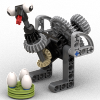
Motorised Johnny 5 MOC <Not an Alternative Build>
RJ BrickBuilds posted a topic in LEGO Technic, Mindstorms, Model Team and Scale Modeling
01 by RJ BrickBuilds, on Flickr Hello, Bozos! You can support Johnny 5 on Lego Ideas to turn him into an Official Johnny 5 Lego Set here: Johnny 5 on Lego Ideas Who is Johnny 5? Those who don’t know him, Johnny 5, also known as “S-A-I-N-T Prototype Number 5” or Number 5 for short, is a very lively and inquisitive military robot prototype who’s perpetually hungry for more “input”. He is the star of the 1980’s movies Short Circuit and Short Circuit 2 and a TV special called Hot Cars. He became sentient when he was luckily struck by lightning during a combat demonstration. Although he is designed to serve the military as a robot prototype, he has an adorable child-like behaviour and has a great respect for life. He is a peace-loving robot and refuses to use his military capabilities to harm others. Despite being very intelligent and inventive, his naivety and trusting nature has been taken advantaged of on several occasions. Design This model is fully motorised using Powered Up motors and hub and controlled through a mobile device using the Powered UP App. It uses Technic parts to ensure stability of the structure, and System parts to capture the look and form of Johnny 5. The following are the playable features of the model: Movement – This model can move around on tank tracks and uses skid steer to change directions. Body – Johnny 5’s body can tilt using a Powered Up L motor and controlled using a mobile. Arms – Arms can be raised and lowered individually using the Powered Up App. The fingers can be adjusted manually as well as the elbows. Head – The head can be tilted and turned using the Powered Up App. Eyebrows – Eyebrows can be manually adjusted to suit the desired facial expression. Laser – The laser at the back can be raised and lowered using the Powered Up App. Watch the YouTube video here to illustrate these functions better: Johnny 5 on Youtube Total Pieces: 2,711 Dimensions: Studs: W 68.4 x L 36.1 x H 73.5 Inch: W 21.5 x L 11.4 x H 23.2 cm: W 54.7 x L 28.9 x H 58.8 Weight: 99.8 ounces or 2.83 kg Johnny 5 MOC Pictures: 02 by RJ BrickBuilds, on Flickr 03 by RJ BrickBuilds, on Flickr 06 by RJ BrickBuilds, on Flickr 05 by RJ BrickBuilds, on Flickr 04 by RJ BrickBuilds, on Flickr 07 by RJ BrickBuilds, on Flickr 08 by RJ BrickBuilds, on Flickr 09 by RJ BrickBuilds, on Flickr 10 by RJ BrickBuilds, on Flickr -
Technic ans Scale models at Bricking Bavaria 2022
functionalTechnic posted a topic in LEGO Technic, Mindstorms, Model Team and Scale Modeling
Hi everyone Last weekend the Bricking Bavaria 2022 took place in Fürth, Germany. LEGO builders from around Europe travelled to Fürth to show their models. This year large cranes, lang heavy load transporters and even a technic locomotive in scale 1:17 were shown. It was really inspiring to meet other builders and learn about their building techniques, concepts and how their model work. For all people who had not the possibility to come to BB22 I cut a video with as many models in action as possible. -
Brick Exhibition Modellbaumesse Ried scale models October 2022
functionalTechnic posted a topic in LEGO Technic, Mindstorms, Model Team and Scale Modeling
Hi everone Last weekend the Modellbaumesse Ried took place together with the LIGA+MP and the AFOL Technic Team action area. I was also there and made a video recap of the action area. New and old scale models were shown. This year the first time a large conveyer belt and gravel plant was presented and was fun to play with our models. The next exhibition with the AFOL Technic Team will take place in Fürth, Germany at the Bricking Bavaria from 18. to 20. of November. -
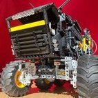
6x4 tractor unit inspired by Scania
functionalTechnic posted a topic in LEGO Technic, Mindstorms, Model Team and Scale Modeling
Hi guys Recently, I finished another model. It is a tractor unit inspired by Scania S-Series trucks. It has 6x4 drive and suspended axles. The front axle is suspended with normal LEGO hard shock absorbers. The rear axles have rubber suspension which imitates air-suspension as used in real trucks. The suspension at the rear axles is a bit hard but chassis is in return flat. The fifth wheel as a self-locking mechanism so that you can couple a trailer easily. To open the fifth wheel a small linear actuator is used. For steering a PU L motor sits directly on the front axle. For propulsion I used two PU XL motors. But check the pictures and video: Instruction at Rebrickable: https://rebrickable.com/mocs/MOC-86508/FT-creations/6x4-tractor-unit-inspired-by-scania/#details -
-kpia.thumb.png.a265cddff9575859eea3a4d2aad663c2.png)
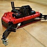
MOC RC Hägglunds BV 206 ATV
Technic BOOM posted a topic in LEGO Technic, Mindstorms, Model Team and Scale Modeling
Please suport my project on Lego Ideas. https://ideas.lego.com/projects/bc17ae38-b3e7-4cb2-b804-401e0bcc7aef Power functions: 3x L-motor 1x IR Receiver 1x IR Remote Control 1x AAA Battery Box 1x Control Switch 1x Extension Wire Description All openable doors. Model have fake motor V6. Color: Black and Yellow Number of Pieces: 800-100 Thank you very much for your support! Military version: Hägglunds BV 206s -

[MOC] 8 Legged Walker Robot
zumaidi posted a topic in LEGO Technic, Mindstorms, Model Team and Scale Modeling
Fully RC 8 Legged Walker Robot https://rebrickable.com/mocs/MOC-85603/zumaidi/8-legged-walker-robot/#details -

42114 Volvo N10 6x4 Dump Truck - alternate build
Timorzelorzworz posted a topic in LEGO Technic, Mindstorms, Model Team and Scale Modeling
100% made out from parts of set 42114 - Volvo Articulated Hauler 100% controllable with official Control+ App This replica of Volvo N10 Truck is an alternate build (B-model) of the set 42114. This means if you own the Volvo Articulated Hauler, you can completely build this alternate model. Other parts from other sets or spare parts are not required. This model of Volvo N10 Truck is a massive biest. It is more than 58 cm long, 20 cm width and 21 cm height. With open bonnet, the model reaches a total length of 65 cm. This alternate model uses 2041 parts, which are more than 93% from the parts of set 42114 Volvo Articulated Hauler. Follow this link for more pictures and content. Visit rebrickable for building instructions. Impressions Doors of the cabin can be opened to access the detailed interior. The bonnet of the Truck is 90 degrees openable to reveal the V6-engine that is linked to the drivetrain. The model uses the gearbox and housing from the Volvo Articulated Hauler. After building step 85 of the Hauler, the instructions takes over to build the Volvo N10. Keep in mind if you disassemble the Hauler, you can leave the built from step 1 to step 85. use of 42114 sticker The alternate model is designed to use stickers from the main model for better look - especially for the front grill. Parts with stickers that show A60H were not used, but the model uses the 3x11 panels with A60H stickers that can be hidden inside the tipper bed. Those four parts with stickers are not required: Battery and Hub access Thanks to the gap between the cabin and the tipper bed, batteries of the hub are easily removable. This requires no disassembling of parts and is done very handy and quickly. The hub is accessable through the cabin, connecting the hub to the App is an easy task. Controllable with C+ App The model is designed for use with official Control+ App and the profile that controls the 42114 Volvo Articulated Hauler. If you are familar with the App and the Volvo, nothing is new here for you, but the alternate model needs a re-calibrating in the settings for steering. If you are new to Control+, you have to download this official App to control the Volvo N10 Truck. With each App interface, the model is completely controllable. Using a third party App to control is also possible. Instructions The instructions for this model are 325 pages long with high quality premium images and different camera angles and views for a satisfying building experience. The instructions will guide you how to connect wires properly and can be found on rebrickable. Here are four example pages of the instructions: The real Volvo N10 To replicate the caracteristic bonnet, cabin, front and headlights was a big challenge. More than 400 parts of the model are placed inside the bonnet. Here are some example pictures of the real Volvo N10 that matches the model most: What makes this model different from 42114? Honestly this model fullfilles with driving, steering, transmission gearbox and tipping the same tasks as the main model with the same App. The Volvo N10 alternate model is a nice looking truck in another scale and again its a Volvo with use of the same stickers. The licensed alternate model is something that you can expect at the back of the box of 42114. Have fun with this alternate build. -

51515 remote control ?
bluatigro posted a topic in LEGO Technic, Mindstorms, Model Team and Scale Modeling
i want to know whitch is better a mobile or a other remote control whitc are there ? pro and cons ? -
 Hi everybody, I'm newbie to the EB, so I'd like to introduce myself with this humble MOC. I'm a fan of LEGO Technic and pneumatics, especially RC ones. I hope I will meet here more fans of LEGO Technic pneumatics. I'd really appreciate any discussion and suggestions. Features: Powered and controlled by BuWizz 2.0 + 2 x Sbrick + PS4 controller + BrickController 2, 16 RC functions (12 can be used at once); 7 x PF motors - 4 x servo motors and 3 x L motors 6 x PF LED RC AWD powered by a PF L motor - with a central differential and gearing including the difference in the wheels’ diameters; pendular driven front axle controlled by PF servo motor - the pivot point is above the wheels’ axle to limit overlapping wheels on the front loader - like in a real tractor; differentials on both axles; 7 RC pneumatic functions controlled by 3 PF servo motors - 3 of them can be used simultaneously (selected manually). 3 at the front to serve the front loader, 4 at the back - one for 3-point hitch, and 3 outputs for additional attachments; pneumatic pump powered by a PF L motor and connected with all RC controlled pneumatic valves. It works proportionally to the opening of the pneumatic valves what ensures smooth work of pneumatic functions. Front loader with 4 attachments - brush grapple, wrapped bale grab, pneumatic sliding pallet forks and bucket; PTO shaft - powered by a PF L motor; trailer hitch; opening hood and doors; lights - front and rear, roof spotlight, blinkers, beacon lights; simple interior - steering wheel and driver seat; Here you can see it in action:
 -

[MOC] Stig's Pickup Lowrider [Free Instructions]
LForces posted a topic in LEGO Technic, Mindstorms, Model Team and Scale Modeling
Hi, guys Remote controlled Pickup with Top Gear Rally Car profile Lambo doors, adjustable height of the rear axle (manual) Download for free at lforces.com Happy Easter! -
Wheel Loader 1:17 scale inspred by volvo
functionalTechnic posted a topic in LEGO Technic, Mindstorms, Model Team and Scale Modeling
Hi everyone After one year I finished another MOC. Here I present my wheel loader inspired by Volvo wheel loader L120H with technic chassis and creator style body. The model is controlled by two Sbricks an powered by one small PF battery boy. The boom and the bucket are controlled with pneuamtic cylinders coupled to a geared servo motor with the newest pneumatic valves. Like this it is possible to control "heavy" loads precisely. Furthermore, the model has an auto compressor which is controlled via the BrickController2 app, where it is possible to add one port of the Sbrick (here the compressor) to two independent other functions (here the two servo motors with the valves). Like this the pump always switches on as soon as one of the pneumatic function is selected. But check the functionality in the following video: Instruction is available on rebrickable: https://rebrickable.com/mocs/MOC-64106/FT-creations/wheel-loader-inspired-by-volvo/#details -

Mini claas xerion rc with BuWizz
Woodstock pl posted a topic in LEGO Technic, Mindstorms, Model Team and Scale Modeling
I present my method of controlling the mini xerion. Along with some aesthetic modifications.I guess I’ll point out the aesthetic modifications first as they are the most interesting I have changed the mud guards, added headlight extensions to the bumper, and added an exhaust stack. How could TLG miss the exhaust stack... Oh yeah three letters, TLG now for the actual post;)I decided to make a trailer to carry all the electronics so as to not clutter up the tractor. The drive is transferred by the universal joint on the bottom, and steering by a combination of cv and universal on top.Here is the layout of the components in the trailer.And now for the driving video. I apologize for the poor quality, as I only have one phone;P and it is used for driving. Any questions or comments, please ask -
[MOC] All-Terrain Winter Expedition Vehicle
teetertater posted a topic in LEGO Technic, Mindstorms, Model Team and Scale Modeling
Hello EB! I'd like to humbly show this remote control (PF) winter expedition vehicle (MOC). Featuring 4 independently driven tracks with a unique steering system. More explanation below and in my YouTube video. It has many issues that I'm not willing to spend more time to fix, but I've learned a lot from the process, which will help improve my future MOCs. If I was to start from scratch here's what I would change: Put motors closer to driven axles Split drivelines into either front/back or single motor per tread less complicated steering system Use a different type of suspension instead of pendular raise the height of the driven sprocket instead of extending driveline with gears reduce weight with panels vs lifttarms (I didn't have any at the time of building) Never use an Adder again, or if I really have to then use the old-style 24t differentials Work more on the cabin/exterior design A sizeable portion of the issues stemmed from the weight, which is something I didn't expect! I ordered some parts to allow me to finish the frame, and added design elements in the meantime. The design elements were pretty much the difference between being-able-to-carry-its-own-weight and not. The MOC is already disassembled, but I'll be happy to hear feedback and suggestions! -

Controlling the Rough Terrain Crane
Skookumjim posted a topic in LEGO Technic, Mindstorms, Model Team and Scale Modeling
I have for a while wondered about using robotic components to automate/control the Lego Rough Terrain Crane ... this has now happened using the Mindstorms Robot Inventor hub with 5 medium stepper motors and a distance sensor ....while keeping the original power functions large motor to avoid further destruction of the original model. One motor switches turntable rotation, another switches the drive from turntable to jib while a third switches power to the original motor. Two further motors switch the six way gear selector for hook and jib. the distance sensor is used to limit turntable rotation to accommodate the relatively short cable lengths. The resulting construction works well.... the crane can both remote controlled and programmed. https://www.dropbox.com/sh/82vqyjvd2zledp0/AAA736uPmlzo9hL-sIWdGS8la?dl=0 -
[MOC] Christmas Tree (of Doom)
teetertater posted a topic in LEGO Technic, Mindstorms, Model Team and Scale Modeling
Hello, I got back into Lego during quarantine and decided to try something unique in the holiday theme. Here's my driving, spinning, Christmas tree. The top part is made with three turntables, with rotation driven by motors at the base. Frictionless pins and/or axles allow the "branches" to raise or lower with centripetal force. I know it's ugly, but I was aiming for a freaky vibe so that worked out Here's a short demo, with some videos of the inner workings too: View from underneath: Side detail closeup More photos: https://www.flickr.com/photos/191824083@N05/with/50858767061/ Happy to hear your feedback and design tips. I lurked this forum for a while and learned many building tricks. -
 Hi again, Especially the Technic Fans part of this community, hosts people from almost all ages, say 9+ So, I think, this is a tough question: What do you think: Should the newer sets have more models which are: * More complex but without motor(s) and/or RC, * More complex and with motor(s) and RC, * Less complex but without motor(s) and/or RC, * Less complex and with motor(s) and RC, * Stay in the same "choice/production system by LEGO" or, * Leave the moddings/mods to the MOC creators? You may say that "it depends", you may say that "the topic is stupidly created because some are more into classic models with lots of mechanical but not motorized/RC parts, some do, so there is no definitive answer to this", BUT, I would kindly like to have your OWN thoughts. For example; I would like to see a Bugatti Chiron Set which has the same complex system, but also being able to be remote controlled and capable of reaching at least 25 km/h. Take this topic like a poll with detailed answers with intra-members-communication, as well. I hope I made myself clear. Many thanks in advance and, Best Regards, Idris
 -

RC Chevrolet Corvette Z06 MOC
Dylan Sebastian posted a topic in LEGO Technic, Mindstorms, Model Team and Scale Modeling
I made this model a long time ago, and I just figured that I'll share it here too. Features: PF RC driving by 2 XL motors PF RC steering by a servo motor PF RC opening doors by 2 M motors working front PF lights Independent suspensions on all wheels Openable hood Working fake V8 engine The white tubes for the body are not official LEGO parts, I bought them in a local supermarket in the party equipment section. The video shows the old version of the model which did not have the doors motorized and the back slightly different. The pictures with white background are the new version. Video: Some more pictures: More pictures: https://flic.kr/s/aHsky5B5Cd Instruction: Google Drive: https://drive.google.com/open?id=0B14dC4ffenNhR1NJa1ZuZGgzVVU Dropbox: https://www.dropbox.com/s/ancnq6nvmtuuaja/Z06.zip?dl=0 -

[MOC] - Power Functions Joystick
Scorpion posted a topic in LEGO Technic, Mindstorms, Model Team and Scale Modeling
I was playing around with power functions remotes, trying to bash out a joystick-style remote control for my latest project, but all my efforts were unsatisfying to me. So I searched around for some designs and I came upon Technic Dragon's excellent design. Having found it to my liking, shamelessly ripped it off drew inspiration from it to make this remote. The design is practically the same, I only made small improvements to decrease the part count. I hope you all find it to your liking as well. Here's the LDD file. Hope you enjoy it! -

[MOC]Nissan Datsun D21 (Hardbody) 1996'
filsawgood posted a topic in LEGO Technic, Mindstorms, Model Team and Scale Modeling
Hi, lovers of Lego! Today I want to show you my new 4x4 MOC - Nissan Datsun '1996 in D21 body. Specifications of MOC Model Lego Technic Nissan Datsun built on all-wheel drive platform, has a beam axle with unlocked differentials front and rear, steering - rack and pinion. The body and chassis are separate elements and are fastened to each other by 4 points. Opened doors, hood and door body. Electrics: LiPo unit XL motor on movement Servo motor - steering IrV2 - Remote control Just want to say that this story of this model, I did not finish and I want to continue it in the back of double cab body. It all began with the construction of low general pickup, its theme, you can see here on EB. By the summer I want to build a second pick-up and take over the full video on the outdoor. I do not really want to ride on the dirty snow right now. -
Dear All, there are numerous contributions on electrifying LEGO train switches, including those here on EB. All-LEGO solutions, all-custom solutions and “everything in between” has been presented. One issue for my layout was: How to control about 30 electrified switch points on a fairly large and rather congested layout with many areas not readily accessible – in a purist solution? Using individual cables going from one single “control center” to the switches would result in some considerable cable mess. Alternatively, PF receivers may serve as remote controllers on “PF layouts” – manipulated via IR light from the center. That is a very elegant solution, however, there are only 4 x 2 IR channels (or 8 x 2 in extended mode with a mandatory custom remote control program), which is not enough on my layout, particularly when running several PF controlled trains eating up channels as well. One approach is a fully LEGO based solution using LEGO programmable bricks (PBricks). With such PBricks one can use a variety of motors on the drives and also some fairly flimsy switch drives because of power and timing control of the drive train. Furthermore, with some software development (e.g., NQC, RobotC, NXC, NXT-G …) the controllers may get their own “address” and operation software. However: Cost may become an issue: You need 1 NXT or 1 RCX for each set of 3 switch drives, or 1 Scout for each pair of 2 drives (in case the drive is operated with one additional MicroScout, the Scout can also operate 3 drives) … More recently, LEGO compatible 3rd party switch drive controllers have become available: The 4DBrix (https://www.4dbrix.com/) varieties are extremely nice! What I find particularly intriguing is the control software. The entire product line from switch drive, controller, to full software integration is the best LEGO compatible solution I became aware of. Nevertheless, here is my all-LEGO “solution”: Brick-built switch drive controllers equipped with PBricks. Please don’t take this post too seriously. It was a lot of fun to build these – plus I like to see stuff moving and making noise (in addition to trains that is) on my layout. Since a video says more than 1000 words, here is the “visual summary” of the rather long write-up following below: And here are some more detailed descriptions ... Working principle The idea of this approach is rather old; in 2007 this article in Railbricks Issue #3, page 44 illustrated some details: The controllers serve more than 3 switch drives with only one PBrick by “mechanical address decoding” – or whatever you want to call it. At that time though I did not think about “simple” motorized switch drives; the ones I used then were all equipped with MicroScouts and were designed to run only with these. That limited the applicability of the controllers on my layout significantly: You need to turn on a MicroScout and put it into “P” mode to let it do what is expected from an electrified switch drive. However many of the switches are hard to get to – hiding behind bookshelves and underneath/within furniture. I have thus added mechanical switch drive controllers for operation with NXT, RCX, and Scout PBricks operating most of the LEGO electrical motors, including PF. So far I have electrified all my switches and bunched them up in “groups” using four such switch drive controllers. What are the controllers supposed to do? They serve as “local remote control hubs” for a group of switch drives. There is essentially only a purely mechanical “bricking” limitation on how many switches can be handled by each controller. The controllers have a dedicated address, for simplicity let’s say address 1, 2, 3; the individual switch drive is hooked up to the respective switch drive controller and has a local “address”, let’s say a, b, c, … The last bit of information required is the switch position, let’s call that “straight (s)” or “turn (t)”. The information sent to all the controllers on the layout is then “controller address + local switch address + switch position”, for example “2, d, t” means that switch “d” operated on controller “2” should go into “turn” position. As shown in these posts here and here, all communication on my layout is via the LEGO IR messaging protocol, mostly transported via RF. Figure 1 shows a “bare” Scout operated switch controller without any decorative stuff; Figure 2 a controller with an additional decorative brick structure remotely matching the Toy Story steam engine coaling station, Figure 3 a controller that is residing within a “building” remotely matching (if at all) the appearance the #10027 train shed – however with a rather “transparent” roof (in fact I got hold of 50+ of transparent #41750 pieces for free and all were left handed … what to do with them?). Figure 4 shows a more or less bare controller I built because I needed to serve 12 switch drives in locations under my desk and further away. All four work on the same principle, but use slightly different mechanical operating techniques. The Scout operated controllers in Picture 1 and 2 use the Scout’s Visible Light Link (VLL) terminal (“Output C”) to connect with MicroScout operated switch drives via an optical fiber link. In my opinion, TLC never really exploited the possibilities of the VLL link. They for example never produced optical fibers longer than about 20 cm, as far as I know. Rather cheap plain vanilla optical fibers (1 m for less than 1 €) are good enough. The controller in picture 3 runs with an RCX PBrick and uses PF switches to operate switch drives equipped with PF or 9V motors. It features a moving stage powered by a PF M motor and a Technic mini motor for actuating the lever throwing the PF switches. The controller in Picture 4 operates an almost identical stage. The stage drive is not mounted on the stage itself; the Scout drives the stage via Technic chain links (#3711) with a stationary #47154 motor and again a Technic mini motor (#43362) for switching. Common to all controllers is the “positioning” mechanism of the moving stage: In case of the optical controllers, VLL light from the Scout output needs to go through the corresponding fiber connecting with the MicroScout operating the switch drive. The fibers are simply pushed through Technic bushes into a Technic brick with holes, in other words they are always nicely lined up. So we just need to get the VLL light from the Scout to the corresponding hole. That is accomplished by either moving the entire Scout PBrick (see controller in Picture 2) or by moving the 20 cm long LEGO optical “fibers” (BrickLink ID x400c20). These are more or less plastic tubes that came with the ExoForce sets – finally I found a way to use them …) connected to the VLL terminal to the target hole, see picture 1. The Scout has a built-in light sensor; that one is used to detect when the VLL output diode is in line with a hole or somewhere in between by measuring the light intensity emitted from a LEGO light brick (9V or PF): When the light from that brick goes through a hole, the detector sees it “brightly”, when it is more or less blocked, it only sees a fraction of the “bright” light. When the “hole detection” mechanism is lined up with the fibers, we are done; this is readily the case when stacking Technic bricks with holes. Basically the same approach is used for the RCX controllers; here we need to get in line with the PF switch levers. When lining up PF switches directly next to each other, the levers are 3 holes apart, and we can use a simple optical positioning mechanism again to get to the right switch. The actuator of the moving stage for throwing the PF switches (see Figure 3 + 4 and video) is partly shown in Figure 6. Since the PF switch has three positions (“forward”, “0”, “reverse”) and the switch drive motor is turned on only for less than a second, the PF switch needs to be swiftly turned back to the “0” position. That is tough to do with powering the actuator motor accordingly. Furthermore, the lever needs to be straight up after switching, as the stage/actuator needs to freely pass the switches when moving to a new target. I have used the fairly tight 6.5L shock absorbers (#73129) to push the actuator back into “0” position after the switch was thrown. As mentioned, the switch is thrown with full torque of the Technic mini motor (PBrick output “full forward/reverse”) as the actuator has also always to push against one of the two springs of the shock absorbers. The output of the PBrick is then put into “float” rather than “stop” mode, so that the motor axle turns freely and the compressed spring of the absorber pushes both the PF switch lever as well as the actuator into “0” position. Programming the PBricks The programs running on the PBricks are rather straight forward. NXT, RCX, and Scout PBricks are all capable of multitasking. In my programs, one task is handling incoming messages. The moment an address is recognized by a PBrick as “my ID”, it listens very carefully for the next message(s) to come in; that one contains local switch address and desired position. The routine puts that message onto a stack, sends a “got that” reply and continues to listen for further messages to arrive. A second task watches the stack: Nothing here, nothing to do. Once there are messages on the stack it fetches one, analyzes it and drives the positioning mechanisms to the appropriate output, sends out either VLL light or briefly operates the PF switch by changing the driving Technic mini motor from “float” (off) to “forward” (or “reverse”) and then back to float. After completion it throws the message away and continues with the next one on the stack. How does each controller know, where the moving stage actually is? Upon startup, the stage is driven all the way to the right, until it reaches the “right limit” touch sensor. Then the light brick is turned on and the trolley moves all the way back to the “left limit” touch sensor. On this journey, the light sensor continuously monitors the light intensity. The brightest light value detected is then considered a “hole”; everything else “in between”. Then the trolley moves back all the way to the right touch sensor and on its way, holes are counted and each switch is thrown to get all switches into the “straight” position. Now we know how many switch points are present, we know they are all set to straight, and we know that we are at position “0”. Upon getting a message, let’s say “turn switch 5” it starts to move left and simply counts up holes. Once it arrives at “5” it stops and is automatically aligned with either a corresponding hole for the VLL output of the Scout or the lever of a PF switch. Then it either sends out the VLL forward/reverse command (Scout) for a given amount of time or it throws the PF switch (RCX/NXT), again for a given amount of time. The switch drive motors are turned on within a “hundreds of millisecond” time frame. This time is adjusted to the requirements of the switch drive. That is basically it. The VB6 program (I am old …) running on my laptop is showing my layout with all the track including switches. Basically the program is one database with some graphics and in/output around. Clicking on one of the switch symbols makes the corresponding real switch change its direction. The program searches the database and finds out which controller is assigned to this switch. Furthermore it finds out to which local output (a, b, c …) that switch is connected on the selected controller. Since the program knows the current status of the switch on the layout it composes a message as described above: Controller address + local switch address + new position and sends that out via the IR tower into RF space. There is a little more to it. To ensure rather secure communication between host computer and remote controller, there is a handshake protocol: The controllers acknowledge messages they understood. If there is no reply, the host control program repeatedly sends out the same messages. If there is still no answer for let’s say five consecutive attempts, a warning message tells that something is wrong. The controllers also have some safety routines – should the stage go beyond the end points it stops operating and sends an SOS message, and do on. Seeing this happen is real fun! However the SOS thing hardly happens at all … Another thing to notice is that MicroScouts go to “sleep mode” when not doing anything for about 10 minutes. So every 9 minutes or so, the stage is driven all the way to the left, then right, recalibrates the light sensor, and then back left, stopping at every hole and let each MicroScout play some sound. So they never fall asleep … and there is even more action on the layout. One thing I am somewhat proud of is that all that functionality is possible with 396 LEGO byte codes on the Scout controllers. The RCX PBricks have monstrous 8 kByte of storage space – I believe you could use an RCX to successfully fly to the moon, land there, play soccer, and safely return. These TLC folks are ingenious. And if you don’t want to run a clumsy computer based control program – learning remotes work also very well for easily controlling more than 30 switch drives. This was already discussed in this post. The number keys “1” through “9” correspond to switch drives 1 to 9. I first press one color key (ID), addressing a particular controller and then swiftly a number key. The controller that recognizes the address operates the corresponding switch drive and puts the switch to the “branch” position. Upon pressing the address and then number key twice, it goes to “straight” … Some files The LDraw mpd files for three controller types (Fig 1 – 3) are here along with the NQC programs here running on the PBricks. The controller in Fig. 4 is in the works). Please see readme files in the directories. Note that you need to have the official and unofficial LDraw parts libraries installed. When opening the LDraw files with MLCad, the program tells you that newer versions of some parts are available. Ignore that, otherwise the model may be corrupted. All LDraw files open correctly with LDView 4.2 and MLCad 3.5 Best regards, Thorsten
-
hi all, I have just started into the world of Lego trains and controlling them with Arduino and i'm afraid it's become somewhat of an obsession! I have always loved Lego and trains since I was a child but could never afford it. I have a son who's 6 and shares my love of trains so I figured now was a good time to start! :-D I have limited amount of Lego at the moment, and have been mucking around in LDD and Stud.io building some signals, etc..this also includes using Arduino to control lights as well as trains..my first try with using some IR transmitter LEDs worked, but not real well which made me wonder whether IR is really the best method of control..I have read alot of comments already from people that RF is really the way to go so I will try that next when the 433Mhz Tx and Rx pair arrive. This led me to think of the next weakest link in the chain..the battery, which only lasts so long and is a pain to have to pull out and change..I know Lego and even third party companies have a rechargeable battery, but I'm buggered if I'm gonna pay $100-120 for each one!!! I've never had any 9v or 12v rail-powered Lego, and the way I understand it, you switch on the control, it powers the rail so much and makes the train go...but what if the rail was powered on all the time and you still controlled the train with an internal controller (like the RF receiver). Any thoughts on this? Sorry if I sound like a noob, since I have no experience with how the track-powered system works. sPy from Oz.
-

[MOC] BR2 - RC Sports Hatchback (Feedback wanted)
MattL600 posted a topic in LEGO Technic, Mindstorms, Model Team and Scale Modeling
Hey guys, I wanted to test myself with non-symmetrical building as before my dark ages I used to always build everything symmetrically. Having just arisen from the dark ages about a month ago, I realized that to fit multiple functions and to utilize space, I realized that this skill was needed. Anyways, the Hatchback is actually inspired by French cars with long(ish) bonnets and the Renault clio V6 with it's rear engine taking up the rear seats... Please watch the video and give me feedback, I need to find great spaces for battery boxes in my later creations haha, Thanks -
[MOD][AMS1] 8258-B Crawler
JTS posted a topic in LEGO Technic, Mindstorms, Model Team and Scale Modeling
Presenting the 8258-B Crawler, Designed and built as an entry for the 'Crawlify your set' contest [AMS1] I'm a huge fan of b-models in general, but the 8258-B has always been one of my favourites due to great looks and an easy to modify. Or so I thought... In the end, I reckon about 85% of the chassis has been custom built. There are two L motors situated just below the cabin. One powers the front axle, one powers the rear. Both axles have differentials because, being independently powered, loss of traction is a lot less likely and it saves my poor pieces from becoming mangled. Because the 8258-B is rather small (read: narrow) I had a lot of trouble designing a front axle that could house a servo motor without limiting the range of suspension travel. Eventually I gave up and ended up modifying this axle to accommodate a differential (well deserved credit to the amazing @Madoca 1977). However with that said, I have made sure the bodywork stays almost 100% true to the original. The only alteration I had to made was to the rear wheelarches to make room for the balloon tyres: Original wheelarch Modified wheelarch: Also, the front winch kept scraping on obstacles I was trying to climb over so I switched this out for a bullbar, however the two are easily interchangeable. Anyways, here's a video of this thing in action. As always, please let me know what you think. Whether it's praise, criticism or telling me off for building ANOTHER red and black model (I have other colours, I swear!!), I'd love to hear it. More images can be found in this bricksafe folder. Enjoy =)