Search the Community
Showing results for tags 'mechanism'.
Found 18 results
-
Here is Mr Moon: Wind the handle, Mr Moon will roll his eyes as another spaceship orbits him looking for a place to land… "Hooray, we’ve planted our flag!" Oh, looks like Mr Moon blew the flag down again! I'll be upfront, I did this for the ongoing LEGO IDEAS 'Out of this World Space Builds' contest. But, It wasn't always mechanised though, I agonised about my initial idea which was just going to be 'The man in the moon'. I thought I could do a simple Brick Sketches in homage to Chris McVeigh. I just felt that it lacked pizzazz! So I noodled about adding Classic Spacemen, and microfigures and flags, but it just felt like a perfunctory attempt. After talking with an artist mate of mine [a muggle or Noffler (Not A Fan oF LEGO) as I like to call them] I decided to try to add some form of movement. Here is a little video of the mechanism I eventually got to work in action: If the video doesn't play properly, it can be found here too (turn off sound though - my kids are doing homeschooling in the background!). I'm kicking myself a little because there was a prototype mechanism using the yellow racks I had and some more dbg and brown technic pieces that I appear not to have documented photographically :-( Someone on IDEAS has suggested adding the option of a cow to replace the spaceship with if you wanted and I love that idea. I'm close to the 250 part limit. Some trimming is possible in the part count of the mechanism I think owing to a lack of parts in my collection. I actually spent about £15 on a couple of Bricklink orders that included the black curved gear racks and a couple of bigger black plates. I'm going to have a play to see if I can figure something out... guess I'll be buying a cow sometime this week! I feel like I need a disclaimer, I realise I don't post much on Eurobricks, I'm more of a lurker here in the last few years (this was after I realised I was saying the same things in a few places!). I do feel bad for asking for support, but I really would appreciate the extra exposure sharing this here hopefully gives my submission. Please accept my apologies if you feel I'm being mercenary by posting this. For anyone who is willing to make a comment or lend support to my submission, my entry can be found here. I appreciate any thoughts or criticism and thank you for taking the time to read my post.
-

[MOC] Mystery Box with Mechanism
Konstrakt_Abstrakt posted a topic in LEGO Technic, Mindstorms, Model Team and Scale Modeling
Hi! Today I present to you my Lego Mystery Box. It is extendable by using a scissor mechanism. What do you think about it? -
Hi, i'm in the process of making a new MOC. It will be a mini assault on Hoth MOC, BUT with a kinetic walking AT-AT as centre-piece. I have parts to somewhat test the walking mechanism, but I don't have enough parts to build the whole MOC, so I can't acquire good footage and test it properly. I'm asking for someone with quite an impressive lego parts collection to build my moc, test it and take some photos and most importantly a video of it. Together we can improve it and eventually put it up on Rebrickable. Any other suggestions and/or improvements are ofcourse welcome as well. I will add a render of the current state of the MOC, just so you have an idea of the finished MOC. Thanks.
-
There was a time that a big piece of brightly colored plastic with some lights on it, gently rocking back and forth, could make us so happy. Coin operated rides are something you grow out of, though, so it has been a long time ago that I enjoyed riding on one of these. Luckily, it turns out that building one is definitely a joyous activity! [MOC] To Space and Back for 50 Cents! by Bert Van Raemdonck, on Flickr The motivation behind this build was the LEGO Ideas "Moments in Space" contest. The objective was to build a small creation in the theme of space. It had to be in the same vein as those small promotional sets you get for free when you spend enough in the LEGO Store or at Shop at Home. I tried to follow this guideline as well as I could, really trying to design a promotional set. One thing I wanted to include, was some kind of mechanical play function. I recently acquired the nutcracker promotional set, and I found myself really enjoying fiddling around with it, endlessly actuating the lever: motion just fascinates me. My mind immediately jumped to the concept of a coin operated kiddie ride, as it moves so hypnotically and since it fills me with warm memories. I started by creating a mechanism that creates a smooth and somewhat realistic motion with a compact mechanism, to keep the build somewhat in proportion with minifigs. In the end, I'm pretty happy with how nice the motion looks, and I'm sure I would play with this endlessly! This motion is made possible with a bar mechanism attached to the sun-shaped dial. I spent most of my time tweaking the positions of the joints to make the motion as realistic as possible. I also used friction pins in the hinges so you can leave it in any position and it will stay in place, so you have more options for display. [MOC] To Space and Back for 50 Cents! - On the Operation of Rockets by Bert Van Raemdonck, on Flickr I also tried to make it as displayable as possible by first of all making it look like an actual kiddie ride such that it should be right at home in a Town layout outside some big store or in a mall. So the rocket got a shape that would be appealing to children nicely fat and round with an interesting shape of the nose (for those who were wondering, the rounded tip of the nose cone is one of those pieces that are the lower half of a balloon), nice lights, a steering wheel that does absolutely nothing but makes all of the difference to children, the typical slanted coin slot and stairs at the back to at least give some explication how that kid got up there. To make it more attractive, I made the base entirely in the space theme. The mechanism isn't actuated by some obvious crank, but by what looks like a sun, which totally blends into the base. All other planets in our solar system have been included as well, with colors and sizes as close as I could get them and a fun little combination of parts to create Saturn. With all of those touches, I hope it looks convincing enough that children would beg their parents for a coin to have a ride on this thing! [MOC] To Space and Back for 50 Cents! - Please, Mummy, Please, Please! by Bert Van Raemdonck, on Flickr That's it! I hope you like it and brought back some wonderful childhood memories! It certainly brought back the same level of enthusiasm for space as when I was a child. Maybe the Falcon heavy launch had something to do with that as well... Anyway, check out all of the contest entries for more spacey fun in a tiny package! ________ The LDD file for this build can be found here.
-

Flying Dutchman "Capstan Hammer" release the Kraken mechanism
scheuerbeutel posted a topic in Pirate MOCs
This is my version of the "Capstan Hammer" of the Flying Dutchman (cf. https://www.youtube.com/watch?v=9gp73EZdObM) if you want to see the mechanism in action visit https://imgur.com/a/g2uad because I cannot upload more than 0,1 MB :/ The most challenging part was to construct the inner part in such a way that it rotates along with it, but can also be lifted and falls down abruptly. In addition, the mechanism should be kept so small that it can be installed in a normally dimensioned ship. Although the rotary movement of the hammer during lifting is not exactly the same speed as that of the capstan, I am still quite satisfied with the result. -

Stepper Mechanism Question
powerwindows83 posted a topic in LEGO Technic, Mindstorms, Model Team and Scale Modeling
hi guys! ive seen many different designs for stepper mechanisms on youtube (...https://www.youtube.com/watch?v=w1Nj-5ISZow...) primarily to be used for shifting transmissions remotely, but none quite achieve what i'm looking for. all of them use a cam attached to a motor that will advance the mechanism by an increment every time the cam executes one revolution. to control these types, the user would have to listen for the click or look for the effects (ie vehicle speed change) to know to stop driving the motor, which if messed up could lead to overshooting the desired number of shifts or possibly breaking something depending on the design. so my question: has anyone developed a stepper mechanism that advances one increment based off of the motor being accelerated as opposed to rotation count? like if i wanted to shift up i would run the motor, and the motor would increment the mechanism but then keep spinning freely until i tell it to stop, at which point it would 'reset' itself mechanically and be ready to shift again when i want? i doubt just throwing a slipper clutch at one would work because of the high force it takes to actuate such mechanisms, and that wouldnt work in most designs since the force of stopping the cam is the same as shifting, therefore a slipper clutch wouldnt do anything or it would prevent the mechanism from ever shifting. any ideas for this? -
Greetings, Train Tech! About a year ago, I posted my Umbauwagen 4yg. Here is the 3-axle variant, the 3yg: The name Umbauwagen means "rebuilt coach" -- these coaches were built after World War 2 by modernizing prewar compartment coaches. More accurately, this is an AB3yg (first/second class) + B3yg (second class) pair -- these cars were nearly always found in close-coupled pairs. A few survive as single units in work trains, painted yellow. The body of the model is essentially constructed the same way as my 4yg model: studs-up construction for the main body (leveraging the train window and the 2x8x2 curved slope), SNOT construction for the doors, the details around the buffer, steps, and corridor bellows. Of course I designed new side frames, and there are a few minor details that are different such as the lights above the end doors of the pair. These cars were painted green in DB service, but as the train window does not come in green I elected to build the 3yg in a different color scheme. I believe that this livery corresponds to 3yg cars used as trailers for the ET 85 electric units -- someone with more knowledge of German railways may be able to shed more light on this. At the time I built the 4yg I also built some test models to research how feasible it would be to build the three-axle variant. However, I ran into difficulties designing the chassis and moved on building the 4-axle variant instead (which had none of these challenges). Earlier this year I circled back and spent some time looking into the problem. The first attempt was to articulate the chassis as 4+2, pivoting the body to reduce the overhang -- a technique I previously used on the tender for my model of the Gr670. However, the Umbauwagen 3yg not only has a long 3-axle wheelbase, but also has a long distance between the outer axles and the buffers: Articulating the chassis as 4+2 would allow the car to negotiate turns, however it would also derail any vehicle attached to it as the buffers swung out widely. Further iteration yielded the general outline of my eventual solution: The center and end axles are connected together with a 6-bar linkage, rather than a rigid frame, allowing the chassis to change shape when traveling through curves. It's important to note that the center axle is actually what actuates the system. As the car enters a curve, the center axle is pushed sideways to follow the curve, which in turn angles the outer axles to follow the curve as well. The track cannot apply rotational forces through a single pair of wheels on one axle, and so a similar design to this one without the center axle would not work. You can see the mechanism here: The outer axles are mounted on 2x2 round bricks riding in a 2-stud-wide channel, allowing them to turn and slide slightly towards the center of the car in turns. I experimented a bit to find the best places for the pivots and a construction that would be light and reliable. In the final model I removed the blue tiles shown in the screenshot, to avoid additional friction and binding in the mechanism. Thanks for following along! As usual, I've uploaded some additional images to a Brickshelf gallery, including some notes on and prototypes of the linkage mechanism. Thanks for reading, and let me know if you have any questions!
-

Compact Lego Gearbox | Door Lock Mechanism
DamonMM2000 posted a topic in LEGO Technic, Mindstorms, Model Team and Scale Modeling
Lego compact gearbox - a super simple and compact mechanism! I originally built this lego technic gearbox for a robotic door lock. You can build this simple lego gearbox through the link below. Features a 1:8 gear ratio reduction using a worm gear. LDD / INSTRUCTIONS — https://www.dropbox.com/s/86hgsg48vijh2b7/Mechanism.lxf?dl=0 Inspired by a gearbox in Sariel's Unofficial LEGO Technic Builder's Guide: https://www.amazon.com/Unofficial-LEGO-Technic-Builders-Guide/dp/1593274343 -
I have an idea to build lift cabin on the side of a modular building. Who can help to build or give a link for mechanism that can lift the cabin up, then stop (or without pause), and then go down. And repeat this cycle. Up-down-up-down... Thank you for your attention
-

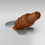
Lego Technic Pumpjack (Oil pump)
filsawgood posted a topic in LEGO Technic, Mindstorms, Model Team and Scale Modeling
Pumpjack - a clear principle of the mechanism. Watch the video, and relax under the spiritual music and mesmerizing movement mechanisms This work is built for the competition "Battle of the Masters in 2016 cube" on bricker.ru site. The main conditions of the competition was to fit the model in size 16x16x16 stud and a ban on the use of the plates. Participants were few, decent work, but as a representative of Technic, I was there alone ... and took the 3rd place. Functional: LiPo unit M-motor Operating principle: Motor through said transmission chain the torque gearbox which converts the rotary motion of the motor into linear motion of the rocker bar. -
I want to build up a set of hopper cars for use at my LUG's next display, and it just so happens that I have six of the 6x28 train bases in orange from my Horizon Express teardown. Even better, they have a couple of 2x2 holes in each to allow cables to pass through, which means I can potentially use them as working hopper cars! Here's what I have so far: Having tested this with a small hopper built out of random bricks and the 1x1 round transparent plates drawer in my collection, the pieces should flow out quite nicely. The problem is the mechanism that will keep these closed and then allow them to be opened again once the hoppers are to be unloaded. So far, I have a device that will keep the doors closed with one of the red Lego pulley bands: ...But that's not really the solution I'm looking for. I'd like something that will operate both doors at once, and lock in either the open or closed position. In addition, I'd also prefer that it operates with as little force as possible, and doesn't require the removal or insertion of any pins - I'd love something that can be pushed over an unloading pit and automatically dump as it passes over, then close up again where it can be taken to the loading station. Oh, and I'm limited to a 4x8x3ish space as well, due to the wheelsets. Shouldn't be too hard for someone with more experience than me, I think... Any ideas?
-
Anyone on here ever heard of a Third Row Seat before? Most station wagons (typically in North America) have them, which converts the luggage area into a third seating area! Here's what mine looks like: Anyone used these in their wagon MOCs before? Thanks for viewing!
-

Back-and-forth rotation wheel mechanism
DraikNova posted a topic in LEGO Technic, Mindstorms, Model Team and Scale Modeling
I've been trying without success to figure out how to make a compact mechanism that translates normal rotation into back-forth rotation. Any thoughts on how to accomplish such a thing? -
Mindstorms Motorized Ev3 Rear Wheel Drive Monster Truck
DamonMM2000 posted a topic in LEGO Technic, Mindstorms, Model Team and Scale Modeling
A LEGO® MINDSTORMS® Ev3 2WD/RWD rock crawler inspired trial truck with live axle suspension, 80 N.cm torque thanks to the special adder mechanism, and more. Built for off-road yet also for speed racing 74 feet in 26.49 seconds (2 mph). For the video please click here: PS-Could someone show me how to embed YouTube videos? Thank you! -
[pid][/pid] Capstans Welcome at my first tutorial here at Classic Pirates, in this tutorial I will try to convince you that there is no argument not to have a functional capstan on your ships. (On condition you have a ship big enough to support one ofcourse and I heard some people are allergic to Technic so I guess that's a valid argument as well). This working capstan design applies perfectly for a frigate in CGH style. I will use a prefab hull for this tutorial but I want you to keep in mind that it can easely be applied to costum hulls as well. This guide will be quite basic because there just are so many different ships, every ship needs its own approach on how to integrate a working capstan. I will start with a simplified construction of a capstan used to haul a singe anchor, then I will extend to more complex and versatile mechanics to eventually allow you to operate two independent anchors. So without further ado, let's get this party started. Operating 1 anchor: You'll need a capstan, it doesn't have to be this one but make sure it connects to a cross axle. But if your really want this one... Another capstan: By Phred An anchor with a winch (also cross axle based). You can use the capstan for other things besides the anchors as well but I'll get to that later. Some usefull technic parts; This is a useful construction; But if you don't have the black part you can use this alternate construction; Now... The implementation of a working capstan takes place at the very beginning of the ship-building process. It's important to place the capstan at the best location of the ship. When starting a new ship I usually start by marking the locations of the masts (I covered them with green round plates to make them more visible). Yellow marks the possible locations of the capstan, keep in mind that the capstan has a volume too so you'll have to reserve some space near the masts. To decide where you will ultimately place your capstan you should consider what else you want in your ship, a staircase and grates perhaps. AT this point you have to know (more or less) how the deck will look. Personally I find it most practical to place the capstan just behind the second mast (on a three mast ship that is), that way I have plenty of room for grates between first and second mast. What I'm going to do now is probably not historically accurate. I will not connect the anchor winch directly to the capstan. I do this for practical reasons, you don't want anchor cables running through the ship, trust me. What I'll do is much more reliable, the anchor winch should be placed as close to the bow as possible (as close to the place where the anchor will hang from the ship), this way there's less chance of complications with rope/cable getting stuck within the ship. Instead of a direct cable connection I will make use of a flexible axle. First attach the capstan to the construction mentioned earlier (this is temporarely, you can detach it later to work on the deck and so on). Then you place this construction in the ship on the place you wanted the capstan (the main reason to attach the capstan already is to make sure it doesn't interfere with the masts). As you can see the capstan is connected to an axle running through the ship. Technic bricks are useful to run through the masts and other obstructions. You may wonder what's the universal joint is for, I noticed some of my ships tend to bend a little when building larger, the joint assures a smooth axle turning. Now the anchor can be hauled up using the capstan. Operating 2 anchors independently: Now in order to provide multiple independent functions to one driving axle, operating two independent anchors with one capstan for example, you'll need a mechanism to shift gears. LEGO Technic provides us with a very easy-to-use system consisting out of these key-parts: Clutch gears: Gear 16 Tooth with Clutch (you need atleast 2). Driving Ring: Driving Ring (you need 1 for each pair of clutch gears). There's also a technic switch available which makes it easier to make the driving ring hatch into the clutch gears: Changeover Catch But I've seen multiple alternatives for that part at the Technic forum, still, I like to use this part over alternatives. In this picture you see the left gear clutched to the axle on top, neutral in the middle (no gears clutch) and right gear clutched at the bottom. connecting the clutch gears with other gears allows you to operate multiple axles, I will now integrate this system in the hull; Note that I just picked a random position of the 'gearbox', you can easely place it practically anywhere, in front of/ after the capstan, in the bow (like I did for my Frigate. Again it's important to think about how your ship will look and what features it will have when choosing a location for the gearbox (The switch was taken out for a better view) The red axle connectors are used to block the gears in one direction, this allows you to pull an anchor while preventing it to fall back down. This isn't always needed though, usually, because the official anchors are so light, the friction alone is enough to keep them up. I used yellow axle connectors to show how to operate the switch, as you can see the lower one allows a rotative motion to switch gears, this means you can attach this end to another flexible axle and thus move the location of the switch away from the gearbox. To illustrate how it works I made this short video: UPDATE: 21 December 2013 The previous construction was built very symmetrically so it would be easier to see how it works. However, when applied to a real MOC ship you don't need to see how it works, the more compact you can build the mechanism, the more space you gain for interior and/or other functions on your ship. I have therefor applied this capstan mechanism to a current WIP of mine to show a more practical example. This is a three-mast ship, the capstan is located after the foremast (very common location for the capstan on a historical ship). The capstan itself will be mounted on the brown vertical axle. The red axle connectors with gray axle towballs are used to block the anchors in place (so they don't fall down after you hauled them). As you can see the gearbox for switching anchors does not lay in line with the ship's length this time. The switch itself is concealed under the yellow technic plate and will be operated by turning the light grey axle. I intend to attach a barrel to the switch axle to hide it on deck in an elegant manner. On this picture you can see the anchor blocking mechanisms, these are connected via several gears to the previously mentioned axle towballs, which will be accessible on deck. Sigh, I really don't get it, when I watch the movie on my camera it's great but when I upload it to my computer it becomes dark . So, this was it, for now. It's my first tutorial so ofcourse it's not perfect, any suggestions to make it better are welcome as well as questions (which may inspire me to expand this tutorial or explain part in a different way). Combine this tutorial with Build a frigate with Captain Green Hair! An interesting link for more about capstans; Capstan by Foremast Jack - - - - - - - - - - - - - I will expand this tutorial later with a sollution for modular ships (yes, a modular ship is not a valid argument not to have a functional capstan so if DPW is reading this... ).
-

World first? Working mini steering wheel mechanism.
Nachapon Lego posted a topic in LEGO Technic, Mindstorms, Model Team and Scale Modeling
This is a home-made version of comic-con 2008 exclusive LEGO Indiana Jones set. Picture of previous modification. MOD steer-able fake Exclusive LEGO Indiana Jones set at Comic-Con 2008 by Nachapon S., on Flickr -

Lego Technic Mobile Crane
legosamigos posted a topic in LEGO Technic, Mindstorms, Model Team and Scale Modeling
Hello Eurobricks members! Today I would like to show you my mobile crane. I didn`t know, that mobile crane is very difficult model to build. I had about 3 months a chassis to my mobile crane, but I spent a lot of time to bulid a tower to this crane. I am glad that I managed to finish my model before the official release of a new set 42009. My mobile crane is full remoted control Specifications of mobile crane: Length: 57 cm Width:19 cm / with the outriggers 33 cm Height: 25 cm / after lifting boom 58 cm / after extension boom 84 cm Length of boom 46 cm / after extension 74 cm Weight: 3130 grams Power Functions: 7 x PF M motor 1 x PF XL motor 4 x PF IR receiver 3 x PF IR remote control 2 x PF battery box Functions: drive for 4 wheels steering outriggiers rotation 360 degrees Functions of tower: lifting boom extension boom, 2 sections winch operator`s cab Lifting weights: BS Gallery Lego site -

Need some help on a lifting mechanism
Carsten Svendsen posted a topic in LEGO Technic, Mindstorms, Model Team and Scale Modeling
I don't have much space to use and the servo motor needs to be lifted from the bottom and up totaling 90° radius. The servo needs to be lifted with pneumatics. I've built this model in SR3D Builder to show you guys. It's not really many pieces so anyone could build it IRL and try to make out something. It should be easily recreateable from the pictures. I'm pretty clueless and I don't know of that many different mechanical solutions with 4 different liftarms or so, so I'm asking for help in hopes that someone would help me