Search the Community
Showing results for tags 'Zetros'.
Found 11 results
-
[MOC] RC Jeep Wrangler - 42129 alternate
gyenesvi posted a topic in LEGO Technic, Mindstorms, Model Team and Scale Modeling
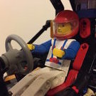
Hey Guys, I'm back with my second alternate model of the Zetros set (42129). As you might remember from the presentation of my Unimog alternate, I was originally entertaining the thought of rebuilding the Zetros into a Jeep, but I passed since Tim has already built one. However, as I kept thinking of how I would do it, it became clear that I had quite different ideas in mind, and it was just too tempting to do it, so I gave it a go. Here I will write down the design process as that seemed to be something interesting for you guys in case of the Unimog as well, and I also prefer such presentations. Features - 3-link floating axle suspension with Panhard rod at the front - simplified rear floating axle suspension with 2 links of limited degrees of freedom and a Panhard rod - 2-speed gearbox with coupled RWD/AWD selector (hi gear is RWD, lo gear is AWD) - smooth and highly colour consistent bodywork - openable doors, bonnet and trunk - detachable hardtop - detailed interior with green accents, built seats - detailed engine, snorkel, minor extras (roof rack, jerry can, fire extinguishers) Here's a real 2-door model in dark grey color which I used as a visual reference: I also used a blue print to roughly set the proportions in a 1:10 scale. Bodywork Interestingly, this model started out from the bodywork, which I don't do often. As a fan of Jeeps, I have long been wondering what the best ways are for replicating its characteristic details, such as the hood and the grill with Lego parts. My Willys Jeep (alternate of the Defender) uses system parts for the (flat) hood and a simple vertical grill, but I wanted to build one with technic panels as well, replicating the slanted surfaces. I have seen two major techniques, one with the long wing-shaped panels (such as the models of @Madoca 1977 and @rm8), and the other with the long curved panel, mainly the classic model of @Sheepo. Since this set has those curved panels in DBG, and the wheels are about the same size as on Sheepo's model, I was wondering if a similar front could be built from the set, especially the angled placement of the curved part, along with the downward slanting of the whole hood, which also needed to be openable. It turned out that with quite a few alterations here and there, the hood could be built, and even better, they could be built using a few large panels only, which makes it look more clean and uniform.. Some arches needed to be redesigned, and the whole became 2 studs narrower, but the proportions worked fine. Then I moved on to the front and the grill, where much more redesign was needed due to different parts available, but after a few iterations with increasing the width and height of the vertical 'bars', I found the one that fit nicely with the smaller lights in the set and the newer curved small panel extenders (and as far as I can tell, newer Jeeps has such bigger grill, so it seemed fine). From there, I moved on to the sides. I knew it was critical to use the BDG panels carefully, because otherwise there would not be enough DBG beams to build the whole body, and I wanted a clean and colour consistent body. I quickly concluded that the doors can easily be built with the large panels, and the windows can also be built with the DBG connectors. The next critical point was to use the thinner long DBG panels in the rear part above the fenders. The difficulty was that they only left one possibility to mount the pieces of the fenders, so I had to use all those black angled beams there, and I had to build the fenders a bit wider so that I can actually connect the two ends to make it a stable piece. Fortunately, the wider fenders also made it possible to build the front ones from black beams at the same angle, even without more available angled beams using triangulation. The last critical piece was to use the small BDG panels in front of the doors, which just fit there tight. If I had to build that section from beams (as I started out), it would have cost too many beams and connecting them to the chassis would have been difficult as well, but the panel solved both problems (unfortunately, it has a drawback as well, which I will cover later). The remaining DBG panels were used in the back, also allowing for an opening trunk. The last tricky part was the rear corners with the lights. I wanted to make them more rounded with the curved panel extenders, but they would have screwed up the proportions, so I just used a slightly curved system brick to give it some curvature. Also I managed to use the black arched beams to replicate the characteristic rear roll bars, and the black tubular parts to build the roll cage, along with the 15L flip-flop beams, which proved to be critical for mounting the roof. The many flat black panels of the set were enough to build the whole roof, along with the side windows in a way that the whole hardtop is detachable from the roll cage as a single piece. Later, when it was more clear what parts remain, I also added the two bumpers, and even a nice snorkel and minimalistic roof racks were doable to give it more interesting details. Gearbox After being satisfied with the rough bodywork, I started designing the functional parts, which I also wanted to put emphasis on, since that's what technic is all about. However, since my Unimog alternate was about the suspension, this time I wanted to focus more on the RC gearbox and build a less articulated suspension which takes less space. I have been tinkering with the idea of a coupled 2-speed gearbox and a central diff-lock for a while (and @Pattspatt also teased me about it), but I never managed to design a compact one, where the drive motors are also placed conveniently. When I looked up a Jeep Wrangler drivetrain, I found this image, which was particularly interesting for me because of the front wheel drive that can be decoupled. Being offset to the side, I thought this could actually be nicely reproduced with lego clutch gears (something similar I already did with my Willys Jeep alternate, not knowing that it's done similarly in real life). After a lot of juggling with the placement of the motors and the gearbox components, I came up with this quite compact drivetrain setup with the gearbox inside the 11x7 frames, which not only includes the drive motors, but the steering motor too (later on that as well). The key ideas regarding the overall chassis structure are the following. First, I use a simplified (limited degrees of freedom) rear suspension, which requires only one CV joint, which makes the rear part of the drivetrain shorter, making more space for the gearbox, which is placed a bit to the back. Second, I placed the motors to the front of the middle section, and use the back of the motors as the mounting point for the front lower suspension links. Thus, the motors play a major structural role in the chassis. Here is the central part: And here is the whole drivetrain without the motors and the frames: As you can see, the rear part is short, and the front is offset to the side, and can just be routed between the drive motors, under the steering motor. Another interesting thing about it, is that it actually has two shafts (yellow axles at the front) coming from the two drive motors (but they are coupled by the red gear in the middle), and one of the shafts powers the 2-speed gearbox, that then goes to the rear axle, and the other shaft powers the the front axle, so the front axle drive does not pass through the gearbox, as it's only active in low gear. The orange selector switches both the gearbox and the RWD/AWD switch at the same time, activating the front of the drive train when low gear is selected. As with my Unimog, the placement of the gearbox motor was again difficult, as a lot of additional elements (end stoppers, clutch gear protection, down-gearing) need to be placed, so the gearbox motor had to be routed out to the trunk. Suspension As I outlined above, the rear suspension is a somewhat simplified live axle. I saw this trick first in @nico71's Ford F150 alternate, but builds of @rm8 use it as well. It is like a ball-joint based suspension, but without the ball-joint as support that prevents the axle from rotating forward/backward. In case of non-motorized models or smaller RC ones with less powerful motors, the joint itself is enough to keep the axle from rotating, but it was not enough in this case (the coupled motors could just rip apart the driveshaft), so I had to fix it explicitly. I opted for a suspension link that does not let the axle rotate forward on the far end, only tilt sideways (not using towball pins, just regular axles). This setup provides strong enough support to prevent the torque from ripping the driveshaft apart. A Panhard rod further stabilizes the axle to prevent sideways movement. Unfortunately, it's still not as solid as a ball-joint would be, and does not relieve all friction from the driveshaft. On the front, I used a similar 3-link suspension as the Unimog, but I had to move the Panhard rod behind the axle as the space was even less in the front, and managed to move the springs further in, giving it a softer and longer travel. It actually came out too articulated and had to be limited, as the wheels hit the fenders. Also, I used a better steering geometry than the Unimog (no anti-Ackermann geometry), and the max steering angle became very good, too good actually, as the wheels hit the bodywork at max angle, and can get stuck in it, so I limited the angle a bit, but is still better than the Zetros (the limiters are just half pins, which can be taken out to get a lot of steering angle, at the cost of risking the front wheel getting stuck in the body at max angle and max articulation, but work pretty good on flat surface). So the suspension is not bad actually, limited a bit by the bodywork, but the model still drives around quite okay on real terrain. Also, I wanted to experiment with a different steering setup, not placing the steering motor onto the axle. As said above, I found it a nice place between the drive motors, and using the CV joints there was just enough space to route it to the axle. It works okay, however, the two joints already introduce some lag in the steering, which is most noticeable when trying to automatically return to center, it does not center totally. But it's still okay and can be controlled with fine adjustments. Interior As the seats in the Zetros set were too small for this scale I needed to build bigger ones. Since I did not want to use the green beams on the outside, I used them as accents on the inside, they were enough to build seats and to be used in the middle console. I entertained the idea of making the steering wheel functional, since the steering motor is not on the axle, but there was not enough space to route it to the steering wheel, and furthermore, the curved panels used as a dashboard just block the way, and otherwise they are important structural elements that hold the front and the sides, so I did not want to alter them. The battery is placed between the B columns, as there was no other convenient place, and there it's easily accessible. The seats can be folded forward, to give room for replacing the batteries. The engine details are just some imaginary ones built from the remaining parts (nothing working). But the snorkel tubing continues on the inside :) Here is the whole chassis with the interior: And here are a few more renders and photos of the complete model, but much more is available on Bricksafe. Building instructions are available on Rebrickable. Let me know how you like it! Cheers, Viktor -
[MOC] Trial Unimog - Zetros (42129) alternate
gyenesvi posted a topic in LEGO Technic, Mindstorms, Model Team and Scale Modeling
Hi All, Although I have posted a few pictures previously, I wanted to make a proper writeup of my Trial Unimog alternate of the Zetros set (42129), because I think sharing the design process is valuable for people around here. Also, I am going to share my thoughts about the set itself as a parts pack. But for the curious ones, here's an action video of the end result and a short summary of the features: Features: - good actual outdoor performance :) - permanent AWD, no differentials - 2-speed gearbox, faster gearing than Zetros - relatively large increase in ground clearance - 4-link suspension on the back, large articulation, soft suspension - 3-link suspension with Panhard rod on the front, slightly larger and softer articulation than the Zetros - opening (and lockable) doors and trunk bed When building alternate models, I always try to build something different from the A model, both functionally and in its looks. So when considering what to build out of the Zetros, keeping the Mercedes brand but going for a different form factor, my first idea was a G-Wagon - quickly taken by Grohl himself. Then I though, let's fall back to a Jeep - also taken quickly by Tim.. Unimog was on my list of potential alternates, but I wasn't sure about it yet. But one thing was sure: I wanted to improve the actual off-road performance over the Zetros. So putting the form factor aside a bit, I started experimenting with chassis and suspension designs. One option I had in mind was to keep the live axle setup, but improve it to make it actually useful for off-roading: increase suspension travel, ground clearance and responsiveness. Furthermore, I wanted to see how lightweight the axles could be built, because the Zetros's axles are pretty bulky. I was okay with doing away with the diff-lock, since I wanted to use the M motor for a 2-speed gearbox anyway (just like others). During experimentation with axle designs and suspension travel, I have realized that the 3-link live axle setup of the Zetros is not only limited by the springs' short travel, but also by the 3rd link on the top. That link cannot rotate sideways on the chassis side and is mounted very high on the axles, and as the axle tilts, its top can move sideways significantly, and as the link cannot follow it sideways, it limits the axle's tilting movement; hence very limited articulation. The setup only works for a short range of movement as on the Zetros, which is limited anyway by the springs, but cannot work for a setup that aims for more articulation. One way out of this is to allow the 3rd link to rotate and follow the side movement of the tilting axle, but then the axle needs fixing sideways. There are two ways to fix that. Either a 4-link triangulated setup, or a 3-link setup with a Panhard rod. Although the Zetros does use a Panhard rod at the front, it is unrealistically mounted and too short, that would cause kind of bump-'steer' for larger axle articulation (not exactly bump steer, but more like shifting the whole axle sideways). So after taking the limited number of suspension parts into account (only 6 towball sockets left out of 10 since 4 must be used for mounting the front wheel hubs, and only 1 6L link available in the set), I opted for the following design: on the rear axle, I used 4 towball sockets for a 4-link triangulated setup with long links, allowing the upper links to rotate sideways and follow the movement of the axle. The springs are attached to the middle of the lower links. This allows for long upwards movement of the axle at the end of the links, and makes the suspension much softer even with the hard springs. Pretty solid and allows for large articulation, just what I wanted. Furthermore, the axle itself is quite slim and rigid, and has good ground clearance, especially in the middle where it's most needed (as proven by my off-road tests). The front axle was more challenging. First off, increasing the ground clearance is only possible with one trick: the towball socket liftarms must be built at an angle, going upwards in the middle, and that limits possibilities. Second, the steering motor and its mounting takes space on the axle, and is in the way for the suspension mounting points. I have experimented with two other options: steering through a driveshaft coming from the chassis, but the placement of the motor in the chassis was problematic do to space required by all other motors and the battery, along with the largely articulated suspension design; second I tried to put the steering motor above the front axle, actuating steering through a linkage system. Although, this worked quite well mechanically (verified with the Powered Up app), unfortunately, the Control+ app itself killed this direction: the app limits the steering motor angle to about a 25 degrees less than the calibrated range, which is normally 90 degrees or motor rotation, resulting in about 65 degrees in case of the Zetros (that's why it's steering is so bad by the way). Now in my alternative steering design, the max calibrated angle would have been 45 degrees, and the 25 degrees minus by the app resulted in about 20 degrees of movement, resulting in almost no actual steering at the axle. Pretty sad that you can build something mechanically sound and then not able to control it with the app :( So I fell back to mounting the motor on the axle, and used the remaining 2 towball sockets for two lower links, which again, I built longer to allow for a bit more articulation. Luckily, I was able to mount the motor in a way that it allowed to use the single 6L link as the 3rd link, allowing free sideways tilting movement of the axle, as it is attached to a towball pin on the chassis end as well. I also experimented with the spring mounting technique of the rear, but it was weak and wobbly on the front without the 4-link setup, so I went back to mounting the springs on the axle. However, I managed to move the springs closer to the center of the axle, resulting in both slightly larger articulation and softer suspension. Finally, the axle is fixed sideways by a long Panhard rod going from one end of the chassis to the other end of the axle, eliminating bump 'steer' quite well even at larger articulation. As a side note about parts, it would be really nice if the set had another 6L link somewhere, for example as a Panhard rod on the rear axle. It could be used to build another 4-link suspension to the front, and also as a steering link in an independent setup (which is problematic to build for other reasons as well). So after sorting out the two axles and the suspension, I though this could be used in a Unimog chassis. Though not too different in form from the Zetros, but at least it keeps the brand. Furthermore, I decided to make it different in its functions: the first step was focusing on a proper suspension. The second was the drivetrain. And that also caused some difficulties. Unimogs are short. You'd think that's not a big problem at this scale, as many RC Unimogs have been built before, but it is with the latest drivetrain parts. The new CV joint with a sliding axle hole is a whopping 8 studs long!! (Compare that to a 3L U-joint; sure, the CV joint has the axle built in on one side, but this construction limits builds quite a bit. Not sure why the new sliding variant needed to be 2 studs longer, I thought it would be just 1 longer, enough for the sliding, which is typically about half a stud, but 1 stud max). So two of those, plus, two non-sliding ones at 6 studs length, and your driveshaft is already 28 studs long. Add to that the amount of space required by the differentials (2 studs on each end until the axle center), and your axle distance cannot be less than 32 studs. Add one more to get a nice odd length middle section, and we are at 33 studs from axle to axle. It is quite long for a Unimog. (As a side note, I tried to split the driveshaft in two halves, shifted sideways in the opposite direction to let them overlap in length and hence make things shorter, but it did not work out due to the axle length limitation of the CV joint part and also space limitations from the motors). So because of this, and other considerations I decided to do away with the differentials altogether. It saves 2 studs in length. It allows for a slightly faster 12T / 20T gearing; the Zetros is just too slow. Furthermore, it allows for larger ground clearance, as the differential does not stick out from the axle. It even allows for a slimmer axle design, as there is more space in all directions, such as for mounting the steering motor. And last but not least: no differential - no need to lock them :) With unlocked differentials the off-road performance would be bad anyway. Once I settled for the length and the drivetrain, I needed to place the remaining motors and the gearbox. I was able to sandwich the gearbox between the drive motors, and put the gearbox's driveshaft motor on top, the flip-flop beams and the frames proved to be very useful for building a strong but lightweight chassis. The final challenge was the driveshaft from the gearbox motor. I am not sure why TLG used this motor here as it is super cumbersome to work with. It needs substantial down-gearing (and the right amount for your actual application, which is 180 degrees final turn for a gearbox, but 90 degrees for a diff-lock), a clutch mechanism for safety and physical end stops for calibration. These all take up space as they need to be routed somewhere. Things would have been much easier with another L motor.. (Maybe to make the set slightly cheaper? Or TLG is trying to get rid of these motors on stock? They don't seem to fit well into the PU system without positional control.) Anyway, finally the chassis of the Unimog was complete. I used the remaining CV joints to connect the drive to the spinning fan in the front :) The rest was just bodywork and placing that big hub somewhere. I opted for roughly the same position in the cab as the Zetros, but with the cables inside, to allow easy access to the batteries for replacement. For the design and styling, I took some inspiration from online sources like this one because of its color scheme, but I wanted to minimize the cab length as there weren't enough panels for a 4-door version. I built the cab with no opening hood to make it solid :) And also made the doors lockable to avoid them opening automatically when driving around.. Finally, the black panels were just the right size and amount to cleanly finish the bed, both the sides and the floor. The bed floor opens (but lockable) to see the gearbox, and to give room for accessing the batteries. I have also added fenders and the usual decoration like the rollbars, exhaust pipe, mirrors, ladders. Here are some renders of the whole build. As you can see, I did not use any green parts, as they would have only added clutter to the otherwise clean bodywork I think. Some more notes about the parts of the set apart from the ones mentioned above. The set has a good amount of paneling and beams and connectors, although the green parts are a bit less useful since they are limited in number and size. Another shortcoming of the set is the available gears. It has all sizes, but their number is lacking in some cases and hence high gearing ratios are hard to achieve. For example if you try to deviate from the default drivetrain, those gears will be missing for example for a simple down-gearing for the gearbox motor.. More images can be found on Bricksafe. Building instructions are available on Rebrickable. I did not know too much about Unimogs in the beginning, but during the research and designed process I actually came to like Unimogs quite a bit. I like that they are compact but seemingly efficient machines, and the trial versions actually look pretty cool. And I am actually quite happy with the end result. Let me know how you like it and your opinion on the set's parts! Cheers, Viktor -

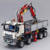
Mercedes Zetros 1833 (42129 MOD)
CrazyKreations posted a topic in LEGO Technic, Mindstorms, Model Team and Scale Modeling
Hey everyone, for a couple of months I've been working on a lego technic camper module that fits on Lego 42129 easily! After a lot of designing, I have come up with a design. I've made a video for all to see and please let me know what you think of this model. This model doesn't affect the Zetros's ability to move in any way (however just to be safe please consider reinforcing the rear axle). It has the following features: Awning Interior with dedicated seating area, bedding and kitchen (kitchen has to be built with bricks haha) rear compartment storage along with a lock Openable windows for ventilation Flexible but sturdy structure for offroading openable door Additional step ladder that can be used to enter the unit Additional storage on the door side of the unit that has a separate compartment to the rear storage space for jerry cans Space for extra wheel -
.thumb.png.116032e930e483fb4ebbfdc62183bd34.png) Hot Trot - RC Trial Pickup w/ Diagonal AWD I would like to present to you my shot at a 42129 B model. About the name 'Hot Trot': On a very uneven surface, a vehicle typically moves its weight from one diagonal pair of wheels to the other as it proceeds from bump to bump. Hence the word 'Trot' in the name of this model. It refers to a horse proceeding at a moderate pace, lifting each diagonal pair of legs alternately. Instructions are on Rebrickable. Diagonal AWD With Diagonal AWD I mean: 1) having two separate drive trains with equal torque that 2) keep a vehicle going on a very uneven surface while 3) preserving the advantage of having a distribution optimal for cornering. We all know the downside of a classic 4WD setup with three open differentials; as soon as one wheel loses grip, all power will flow to that wheel, causing the vehicle to lose traction. One way to deal with that is to add differential locks like in the Zetros. Another approach that is commonly seen in LEGO Technic builds is to have separate drive trains for front and rear wheels like in the 42099 X-treme Offroader, in which case you need a slipping front wheel and a slipping rear wheel to completely lose traction. This approach however, has two downsides: There is no open distribution of torque between front and rear wheels, which is not optimal for cornering, because the front wheels are not free to average to a higher speed than the rear wheels. On a very uneven surface, for instance in diagonal tests, where wheels start losing contact with the surface, it's likely to have a front and (diagonally opposite) rear wheel loose traction. But what if we would separate the drivetrains diagonally: A drivetrain with a differential between the left front (LF) wheel and the right rear (RR) wheel, and a drivetrain with a differential between the right front (RF) wheel and the left rear (LR) wheel? The resulting 'Diagonal AWD' would serve two major benefits: While cornering, the LF and RR wheels will average to a speed that is almost equal to the average speed of the RF and LR wheels. So not having an open distribution between two diagonally arranged drivetrains is much less of a problem than with separate drivetrains for the front and rear axles. On a very uneven surface, where wheels start losing contact with the surface, the wheels that still have contact are typically lined up diagonally. With Diagonal AWD, the vehicle will still have traction, even without additional differential locking. The vehicle will only lose traction when two wheels at one end or at one side will lose grip. Drive trains I wanted to have the motors at the same level as the rest of the drivetrain to keep the center of gravity low. I came up with a fairly flat setup with longitudinally placed motors, a differential at the heart of each drive train and bevel gears to make the 90 degree angles towards the wheels. Each motor drives a 16t clutch gear locked to the differential using a 'floating' driving ring. After some trial and error the best option to properly brace the bevel gears that make the 90 degree angles to the wheels, turned out to be a symmetrical setup with the motors rotating in opposite directions. Because of these opposite directions, using a clutch gear to make the drivetrains cross in a completely flat layout, was not an option. The clutch gear would rotate in opposite direction compared to the axle it's attached to, which would give loads of friction, particularly in motorized models. But luckily, the Zetros has exactly the right gears to make the drivetrains cross independently. The biggest challenge was to prevent the gears that make the 90 degree angles from slipping. I've experimented a lot, but no matter how strong I braced the bevel gears, I could always make them slip with my bare hands, using 24t gears to put force on the axles. So the goal was to make sure the gears can at least handle the power provided by the motors without slipping, even when one drivetrain gets completely blocked. I eventually succeeded, but it has cost me long hours of tinkering and trial and error. I created completely locked up structures for the bevel gears, using the 4 available 5x7 frames and 8 of the 11 beams with alternating holes. These structures are also tailored to fit the main structure well and to provide form-locked mounting points for the suspension arms. The two assemblies are extremely hard to build, because you can only insert the gears and axles after the structure has been put together. Suspension I incorporated independent double wishbone suspension with the springs arranged in a pushrod style. The springs have been mounted such that they compress by approximately 33% under the vehicle's own weight. This gives a very nice road holding, because the springs can both expand and compress while taking bumps. I managed to optimize the spring setup for max suspension travel, which is about 3L, which fitted my objectives perfectly. The suspension travel shouldn't rule out the chances of having a wheel coming loose from the surface, because that's when the Diagonal AWD kicks in. It seemed obvious to use the new longer male half of the CV-joints for the rear axles, so the rear axles use 8L suspension arms. The suspension arms of the front axles are shorter, because I had to build the gear-rack assembly around the drivetrain axles and wanted the steering links to have the same length as the suspension arms to avoid bump steering. The steering setup has an Ackermann geometry. The steering links have been reinforced such that they never detach from the gear-rack assembly and the gear-rack assembly itself has been braced in a way that rules out unintended transversal movement. The 2 phone handsets came in handy for this purpose. Chassis and bodywork The main structure is as stiff as I could possibly make it. I even used the motors as structural elements to add to rigidity. I wanted to rule out flex as much as possible, because I wanted to demonstrate how responsive the suspension is and because a flexible chassis would reduce the chances of the Diagonal AWD kicking in. Apart from the extensions necessary to mount the springs, the main structure is just 5L tall. On top of this main structure I've build a strong structure for the cabin of the vehicle. The bodywork does not have any features like openable doors or whatever. People that know me, know that I'm mainly interested in drivetrains and suspension. The bodywork is robust however and I did pay attention to the interior this time. You can lift it by the roof and I also made it very easy to remove the battery box. Powered Up Profile Because I don't use the medium motor, and because I have the large PU motors running in opposite directions, I could not use the Control+ app to operate this model. However a default profile in the Powered UP app could be easily tweaked to what this model needs: Finally I want to mention that I started using Energizer Ultimate Lithium Mignon batteries for my MOCs. They are strong, long-lasting and most importantly; they are at least 20% lighter than alkaline batteries. Photos
Hot Trot - RC Trial Pickup w/ Diagonal AWD I would like to present to you my shot at a 42129 B model. About the name 'Hot Trot': On a very uneven surface, a vehicle typically moves its weight from one diagonal pair of wheels to the other as it proceeds from bump to bump. Hence the word 'Trot' in the name of this model. It refers to a horse proceeding at a moderate pace, lifting each diagonal pair of legs alternately. Instructions are on Rebrickable. Diagonal AWD With Diagonal AWD I mean: 1) having two separate drive trains with equal torque that 2) keep a vehicle going on a very uneven surface while 3) preserving the advantage of having a distribution optimal for cornering. We all know the downside of a classic 4WD setup with three open differentials; as soon as one wheel loses grip, all power will flow to that wheel, causing the vehicle to lose traction. One way to deal with that is to add differential locks like in the Zetros. Another approach that is commonly seen in LEGO Technic builds is to have separate drive trains for front and rear wheels like in the 42099 X-treme Offroader, in which case you need a slipping front wheel and a slipping rear wheel to completely lose traction. This approach however, has two downsides: There is no open distribution of torque between front and rear wheels, which is not optimal for cornering, because the front wheels are not free to average to a higher speed than the rear wheels. On a very uneven surface, for instance in diagonal tests, where wheels start losing contact with the surface, it's likely to have a front and (diagonally opposite) rear wheel loose traction. But what if we would separate the drivetrains diagonally: A drivetrain with a differential between the left front (LF) wheel and the right rear (RR) wheel, and a drivetrain with a differential between the right front (RF) wheel and the left rear (LR) wheel? The resulting 'Diagonal AWD' would serve two major benefits: While cornering, the LF and RR wheels will average to a speed that is almost equal to the average speed of the RF and LR wheels. So not having an open distribution between two diagonally arranged drivetrains is much less of a problem than with separate drivetrains for the front and rear axles. On a very uneven surface, where wheels start losing contact with the surface, the wheels that still have contact are typically lined up diagonally. With Diagonal AWD, the vehicle will still have traction, even without additional differential locking. The vehicle will only lose traction when two wheels at one end or at one side will lose grip. Drive trains I wanted to have the motors at the same level as the rest of the drivetrain to keep the center of gravity low. I came up with a fairly flat setup with longitudinally placed motors, a differential at the heart of each drive train and bevel gears to make the 90 degree angles towards the wheels. Each motor drives a 16t clutch gear locked to the differential using a 'floating' driving ring. After some trial and error the best option to properly brace the bevel gears that make the 90 degree angles to the wheels, turned out to be a symmetrical setup with the motors rotating in opposite directions. Because of these opposite directions, using a clutch gear to make the drivetrains cross in a completely flat layout, was not an option. The clutch gear would rotate in opposite direction compared to the axle it's attached to, which would give loads of friction, particularly in motorized models. But luckily, the Zetros has exactly the right gears to make the drivetrains cross independently. The biggest challenge was to prevent the gears that make the 90 degree angles from slipping. I've experimented a lot, but no matter how strong I braced the bevel gears, I could always make them slip with my bare hands, using 24t gears to put force on the axles. So the goal was to make sure the gears can at least handle the power provided by the motors without slipping, even when one drivetrain gets completely blocked. I eventually succeeded, but it has cost me long hours of tinkering and trial and error. I created completely locked up structures for the bevel gears, using the 4 available 5x7 frames and 8 of the 11 beams with alternating holes. These structures are also tailored to fit the main structure well and to provide form-locked mounting points for the suspension arms. The two assemblies are extremely hard to build, because you can only insert the gears and axles after the structure has been put together. Suspension I incorporated independent double wishbone suspension with the springs arranged in a pushrod style. The springs have been mounted such that they compress by approximately 33% under the vehicle's own weight. This gives a very nice road holding, because the springs can both expand and compress while taking bumps. I managed to optimize the spring setup for max suspension travel, which is about 3L, which fitted my objectives perfectly. The suspension travel shouldn't rule out the chances of having a wheel coming loose from the surface, because that's when the Diagonal AWD kicks in. It seemed obvious to use the new longer male half of the CV-joints for the rear axles, so the rear axles use 8L suspension arms. The suspension arms of the front axles are shorter, because I had to build the gear-rack assembly around the drivetrain axles and wanted the steering links to have the same length as the suspension arms to avoid bump steering. The steering setup has an Ackermann geometry. The steering links have been reinforced such that they never detach from the gear-rack assembly and the gear-rack assembly itself has been braced in a way that rules out unintended transversal movement. The 2 phone handsets came in handy for this purpose. Chassis and bodywork The main structure is as stiff as I could possibly make it. I even used the motors as structural elements to add to rigidity. I wanted to rule out flex as much as possible, because I wanted to demonstrate how responsive the suspension is and because a flexible chassis would reduce the chances of the Diagonal AWD kicking in. Apart from the extensions necessary to mount the springs, the main structure is just 5L tall. On top of this main structure I've build a strong structure for the cabin of the vehicle. The bodywork does not have any features like openable doors or whatever. People that know me, know that I'm mainly interested in drivetrains and suspension. The bodywork is robust however and I did pay attention to the interior this time. You can lift it by the roof and I also made it very easy to remove the battery box. Powered Up Profile Because I don't use the medium motor, and because I have the large PU motors running in opposite directions, I could not use the Control+ app to operate this model. However a default profile in the Powered UP app could be easily tweaked to what this model needs: Finally I want to mention that I started using Energizer Ultimate Lithium Mignon batteries for my MOCs. They are strong, long-lasting and most importantly; they are at least 20% lighter than alkaline batteries. Photos -
 We have a strong local LEGO truck trial scene, so it was only natural to compare how the $300 official LEGO trial truck compares against the stuff these guys build at homes. As a bonus, you get to see what appears to be a fatal design flaw in Zetros' drivetrain.
 -
My review is below, lengthy but the speed build takes a lot of time and there are chapters for your convencience. Will write more whan I have time, and the 42128 video review is coming tomorrow. Also coming shortly: the 42129 detailed outdoors test and 42129 competing against custom-built LEGO trial trucks.
-

Imanol BB´s MOCs and MODs (And possibly good ideas)
Imanol BB posted a topic in LEGO Technic, Mindstorms, Model Team and Scale Modeling
Hello people, as i have seen some topics made by some members were they share their creations, modifications and ideas, i thought it was a good idea to start my own topic about that, this way i can avoid filling other topics with too many information by saving all that information here and just posting small texts in those other topics. To start, i would like to share some creations which i worked on: Model Team Nissan Frontier. This is one of my oldest models, i made it even before i knew about Eurobricks, and i would like to share it with you because you might like it or modified it: This model features front independent suspension, rear leaf spring suspension using 5.5 axles, HOG steering, working doors, bonnet and tailgate, 5 seats and a towing hitch; its very possible that some parts are with wrong colors or there could be outdated building techniques, but i think that is not too bad for one of my first LDD models (i am no sure, but if i have enough time and inspiration i could make it in real Technic parts), The LXF: http://bricksafe.com/files/imanol/nissan-frontier/Nissan Frontier.lxf. Model Team Paramount Group Marauder MRAP. Again, one of my oldest models, it is made at a pretty small scale but it could still be considered as "model team" (i think), it has pendular suspension in both axles which are damped by cross-axles which act as leaf springs, it has HOG steering, working winch and doors, a spare tire and 2 turrets that can be mounted on the roof: The LXF: http://bricksafe.com/files/imanol/paramount-marauder/Paramount Group Marauder.lxf Technic Unimog U500 Long Chassis (I have called it UNI-MOC) You might have seen it in the latest posts at 8110´s Mods topic ( http://www.eurobricks.com/forum/index.php?/topic/57543-8110-unimog-mods-and-improvements/&page=78 ), it is a 64 studs long and 24 studs wide model which i started to make because the modifications in the 8110 got to a too high level and i wasn´t satisfied with the whole model, i created this new model to hold all of my wanted functions and details, this model has some designs from other builders: Madoca´s Tatra 2-speeds gearbox (slightly modified to fit in this new chassis), Efferman´s planetary rims, a modified version of Didumos knob gear driven axle and a 3-side dumping system and dropping sides inspired by Kumbbl´s modifications, it was also made by some help and inspiration by Pat-Ard: This Unimog has 4 M-Motors, 2 L-Motors, 2 XL-Motors, 3 IR RC Receivers, 2 AAA Battery Boxes and 3 PF Switches (brick-built with ugly colors), why so many motors? well, as you might know, the 8110 had only one M-Motor inside it, which was meant to drive the 3 main functions of the set (front PTO, rear PTO and the pneumatic pump) the problem was that the functions couldn't be used simultaneously, you couldn't power front and rear PTO´s at the same time or with the pneumatic pump and because this system uses a gearbox and axles to engage and transmit the power to the different parts, this results in a lot of friction and power losing (other of the reasons of why i started this MOC), other thing that bother me about the 8110 was the proportions of it, it was very tall with lifted wide axles, but very thin cab and bed which made it look silly, the chassis had no space for all the functions that i wanted, i couldn't place enough motors or functions on it, and the axles were another problem, the steering pivot and angle was a disappointing, the tires couldn't steer too much with the half pins, and if you removed them, the mudguards and the surrounding elements needed to be placed far away from the tires to avoid them from colliding, these are few of the reasons of why i started to make my own version of this UGN class of Unimog (which are U300, U400 and U500). Some of the good features of this model are: Improved steering pivot (2 studs closer to the wheels compared to standard portal hubs) Wheels and portal hubs can handle more torque without jamming parts The axles are more compact (less tall), so the chassis can move even lower for a more realistic performance Front steering by L-Motor Rear steering (By M-Motor) with the same axle design as the front one Anti-roll bars in both axles, which help a lot to handle with weight and give a lot of stability, and they can be easily removed for serious offroading Remotely shifted 2-speeds gearbox by M-Motor Directly driven pneumatic pump (L-Motor) and PTO´s (M-Motors) for less power losing 3-side tipping 37 studs long 23 studs wide dump bed with dropping sides using a V2 large pneumatic cylinder Drive by 2 XL-Motors So, these are some of my models, i hope you like them, and i hope to upload more of them, i will try to do my best with all them, let me know what you think about this topic and the models, and any suggestion is well received Thanks. -
 Today I like to show you my latest MOC: The Mercedes Zetros 1833 Expedition Truck 4×4. It's my second LEGO Technic Zetros in an approximate scale of 1:13.5. The construction time was actually only three weeks. Then the truck was finished by and large. The extensions and improvements took another 11 months. For the impatient among you, here's the video first: This MOC was originally designed for lightweight construction, best off-road capabilities and adequate speed. Therefore I completely redesigned the chassis and the axles. And because it has to work in forest, desert, arctic and jungle, I designed the chassis and drive as simple as possible. Each wheel of the 4×4 truck is driven by an XL engine. Via a 90° deflection via knob wheels, the drive goes to planetary gear. Thus the highest possible torque is available at the wheel. The steering is done by a servo motor. Two SBrick are used to control the truck. In addition, a Power Functions infrared receiver is installed. The Zetros draws its energy from two large PF battery boxes. The lightweight construction was not quite successful. The Zetros weighs 5.7 kg including batteries. Therefore I had to reinforce the springs several times. Now the long red springs are in front ( a bit softer ). In the back there are four yellow, hard springs as well as two spring-loaded shock absorbers. The shock absorbers were necessary because the body quickly built up during off-road driving. So the truck is very stable and easy to drive. About the functions: At the front of the Zetros there is a cable winch with pulley and hook. The winch is operated via one of the SBricks. In the rear of the fully equipped superstructure there is a garage for an ATV. I control its winch via the PF IR. The ATV is quasi a “MOC in the MOC” and of course fully functional. It has a fake V2 engine and rear axle suspension. For a long time I worked on the retractable awning. This stretches itself. The motor, which is hidden in one of the built-in cabinets, only rolls in and out the fabric. The awning is also controlled via the PF IR. A real highlight is the lighting of the truck. Functioning front and rear lights go without saying. The indicators also work on the left and right as well as on the “warning lights”. There is a floodlight bar on the roof. And because it is equipped with an odd number of single LEDs, there was one left. Well, now the truck even has cabin lighting. For interior design. There is a passage between the driver’s cab and the superstructure, as in the original, which is covered at the top and sides with a flexible rubber bead. In the living area there is a loft bed (above the ATV garage), a small bathroom with a suggested toilet, a suggested kitchen block (which hides the winch for the ATV), a closet (which hides the mechanics for the awning), a table and two storage compartments (one is empty, the other contains the awning shaft). On the roof of the driver’s cabin is a luggage rack with two expedition boxes (what’s inside, I reveal in the Behind-the-MOC video) and three canisters of water and diesel (what else). I hope I haven’t forgotten anything. More photos of the finished Mercedes Zetros 1833 and the Work in Progress of the Zetros can be found on my Flickr channel.
 -
 Hi everybody. last month I started a new project, while my 42043-C Unimog U4000 is on standby. I kinda like the Mercedes Benz team. so this one will be another Zetros. while my 42043-C Zetros was a C-model, this Zetros 3643 AS 6x6, will be way bigger, and not a C-model. Below is the blueprint I'm actually building from. been during a lot of research, blueprints and calculated a proper scale many times..... so by basing the scale on the wheels I figured out that a 1:12.5 scale would fit very well. I got some RC wheels 108mm, which kinda looks like the Zetros tires, but the Claas Tractor tires will fit the model very well too. Now let me show some pictures of my actual model so far. This one was my first atempt to build a proper fitting chassis for the Zetros But after a month with rebuilds and testing, I got to scrap that design, as the gearbox wasn't strong enough to power 3-4 kg of lego. also was the chassis a bit to flexible. so during january I ended up with this design: And by now I have finished most of the chassis, on moved on to the cab. As told it is the CrewCab model I'm building, mostly because it is the one I like most, and think it fits the size of the truck very well. By finishing the Chassis, it also means that bumbers and headlights are done. I'm not quite sure about the headlights yet, but it will work for now. The picture above, is the current prgress. More will follow. more pictures at: https://flic.kr/s/aHskRFHEQB
 -
42043-C MB Zetros [MOC
madsen1997 posted a topic in LEGO Technic, Mindstorms, Model Team and Scale Modeling
Hi! Today I finished the 3d model of 42043-C Zetros, so the complete instruction files is on the way! ..... This is my very first Moc that I have published, but the project isn't 100% finished yet. Got the 42043 Set last year, and then decided to rebuild it into an alternative build [C-Model] This is how the model looks like now, it needs a touch before it's done. The model is based on the real life Mercedes Benz Zetros. Technical detail will come as soon as possible, but here is some picture of it. Like the 42043-A this model has a pneumatic crane without the buckets. the crane is build with one pneumatic hose going through the turnable, It allows the crane for turning 4x360 degrees without damaging the hose. 4 valves is mounted at the back of superstructure for controlling the 3 pneumatic cylinders. Crane lifting capacitet: 200 grams of lego[full exspanded] Outriggers been rebuild too, because those on 42043-A had some issue under load. these ones are build like those on 8110, But also allows to fold the outrigger-leg upsite for better clearence. Outriggers arms is controlled independ [2 functions]because of the missing feature with tilting the Flatbed. Battery Box mounted at the back of the cab. with a openable cover. Steering is build like on 42043, and controlled by the 2 beacons. the cabin was hard to build with the few white parts in the 42043 set, but I think i maded i pretty good. UPDATE will come soon! Some facts Lenght: 64 studs ( 52 cm) Wide: 19 studs ( 15 cm) Hight: 26 studs ( 20 cm) [folded crane] Ground Clearence: 3 studs ( 2.4 cm) Weight: will come today Pieces in use: 2399 6x4 Full suspension on all axles Parts: 2300~2500 Openable doors and hood Foldable outriggers Single pneumatic hoses connection ( making the crane rotate 1020 degrees) 3 valve 1 input valve Crane lifting capacitet: 100~200 grams of lego Steering from the ledt beacon on the Roof Model is RC ready -
Help needed for Lpub [Lpub not showing submodels]
madsen1997 posted a topic in Digital LEGO: Tools, Techniques, and Projects
Hi! I'm working on my instructions for my 42043-C model. but i have some problems with lpub. been making the 3D file in both MLcad and LDcad and it worked fine until I added some pneumatic hoses in LDcad. After adding the pneumatic hoses Lpub is not loading any of my submodels, but only the main file. main file is a [MPD] file, and all the submodels incl the pneumatics are [LDR]files. this is how it looks when opening the complete file in LDcad: Skærmbillede 2016-05-06 21.29.12 by Madsen's Technic Workshop, on Flickr but here's what it looks like when opening the file in Lpub: Skærmbillede 2016-05-04 20.13.45 by Madsen's Technic Workshop, on Flickr only LDcad and LDview is loading the complete file with no errors, MLcad is crashing and Lpub is only loading the half. I simply have no clue why it is doing this, so I asking you guys, anyone knows what I'm doing wrong all files I been using for my build is at this link